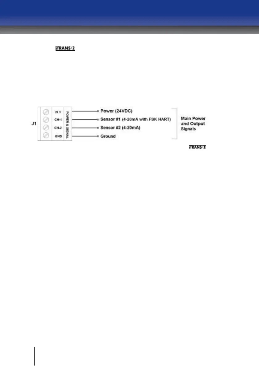
Connect the power and signal wires to the appropriate wiring
terminals as follows.
24 V: Connect 24 VDC (12-28 VDC) supply power
CH-1: Channel 1, HART 4-20 mA output signal
CH-2: Channel 2, 4-20 mA output signal
GND: DC return
Figure A - 6 Power and Signal Connector J1 on HART Supported
HART 4-20mA Wiring (CH-1)
CH-1 and GND on J1 connector are used as HART 4-20mA interface
terminals. The HART 4-20mA output must be loaded with at least 250 ohms
of impendence to properly establish the HART communication. Some
devices receiving the 4-20mA output already have a large enough
terminating resistor installed from the factory, but others may need
additional resistance to be added. This is accomplished by adding a resistor
in series with the output from HART board, preferably at the controller end
of the 4-20mA current loop. Adding the additional resistor at the controller
allows the HART handheld device to be connected anywhere in the loop,
because it must have the full 250 ohm load after its connection point to
function properly. If the additional resistor is added at the transmitter, in CH-
1, the HART handheld device will only be able to access variables locally, at
the transmitter.
The Figure A - 7 shows a 150 ohm resistor added to the output loop since
the controller has a 100 ohm terminating resistor installed from the factory.