~
o
:=
z
o
u
w
I'
eo
z
Vl
=>
~/
~
~
Fig. 36
Fig. 37
Fi
g.
38
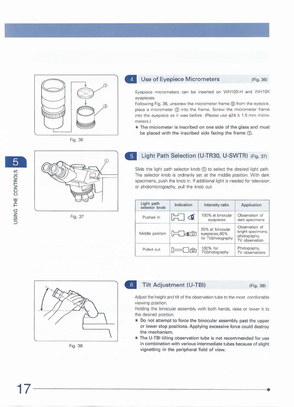
• Use
of
Eyepiece Micrometers
(fig.
36)
Eyepiece micrometers
can
be
insened on WHlOX-H
and
WH10X
eyepieces.
Following Fig. 36,
unscrew
the
micrometer
trame
(1)
from
the eyepice.
place a micrometer
CD
into the frame. Screw the micrometer frame
in
to
the
eyepiece
as
it
was
b
efore
.
(Please
use
412
4 X
1.
5
mm
mi
cro-
mete
r
s.)
* The micrometer is inscribed on
on
e side of the glass and must
be pl
ac
ed
with
the inscribed side facing the frame
(1).
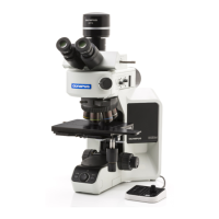
til
Light
Path Selection (U-TR30, U-SWTRl (
Fi
g. 37)
Slide the fight path s
el
ector knob
<D
to
select
th
e desired light path,
The
selector knob is o
rd
ina
ri
ly set
at
the middle
po
si
ti
on.
With
da
rk
specimens. push the
kn
ob in. If additional light is needed for televisi
on
or photomicrography. pull the knob out.
Li~h
t
pa
th
sa ector
kno
b
Indication
Inte
nsity
ratio
Appli
cation
Pushed
In
[;:=::::J
<G:
100%
al
binocular ObsefvaIIOl'l
of
eyepieces dart specimens
20% 8t binocular
ObservatIOn
of
Middle positIOn
G=8:a:@
eyepieces.
80
%
bright specimens.
photography.
f
or
TV/photography
TV
observation
Pulled out
G===CJ
@
100% for Photography.
TV/photography
TV
observatIOnS
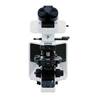
..
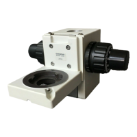
Tilt
Adjustment
(U-TBIl
(Fig. 38)
Adjust the
he
ight
and
tilt of t
he
obseNat
ion
t
ube
to th
e most comfortable
vi
ew
i
ng
pOSition.
Ho
lding the binocu
la
r
a s
semb~
with both hands,
raise
or lower it
to
the
deSired
position.
* Do not attempt
to
force the binocular assembly past the upper
or
lower s
top
poSitions.
Applying
exc
es
sive force could destr
oy
the m
ec
hanism.
* The U-TBI
tilting
observation tube is
not
recommended for u
se
in combination
with
various intermediate
tub
es because
of
slight
vignetting in
the
peripheral field
of
view.
17
----------------
--------
--~
·