15
GX53
Make a copy of this flow chart and diagram, and place it near the microscope so that you can use it when
operating the microscope.
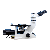
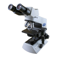
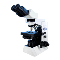
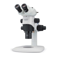
Main switch (P.16)
BF/DF selection lever (P.17)
Eyepiece/camera light
path selection knob (P.18)
3
Light path selection knob
on trinocular tube (P.18)
3
Y-axis knob (P.19)
X-axis knob (P.19)
Stage center plate (P.19)
4
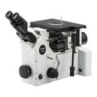
Filter slider insertion slot
(P.28)
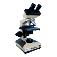
Diopter adjustment
ring (P.23)
Interpupillary distance
adjustment scale (P.23)
9
Field diaphragm lever (P.27)
11
Aperture diaphragm lever (P.26)
Filter slider insertion slot
Coarse focusing tension
adjustment ring (P.21)
Coarse focusing knob (P.21)
6 10
,.
Coarse focusing tension
adjustment ring (P.21)
Filter slider insertion slot
(P.28)
12
Filter slider insertion slot
Filter slider insertion slot
Revolving nosepiece (P.20)
,
Polarizer insertion slot (P.35)
Analyzer insertion slot (P.35)
Provided on the right side
as well
Scale slider insertion slot
Coarse focusing knob (P.21)
,
Fine focusing knob (P.21)
6 10
,
Brightness control knob (P.22)
,
Polarizer insertion slot (P.35)
Scale slider insertion
slot
Fine focusing knob (P.21)
6 10
,
 Loading...