27
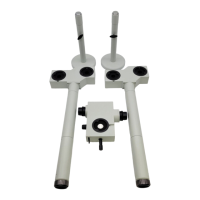
Attach U-MDO10B3
a
on the top of U-MDO10R-3 (at main observer
position) and tighten the clamping screw
b
to secure U-MDO10B3.
Attach U-MDO10B3
a
so that the clamping screw
b
of
U-MDO10R-3 and the clamping screw
c
of U-MDO10B3 are
aligned in one line perpendicularly.
1
See "Attaching the side viewer" in "5-2 Side by side observation
system for 2 persons and system for 5 persons" (page 19).
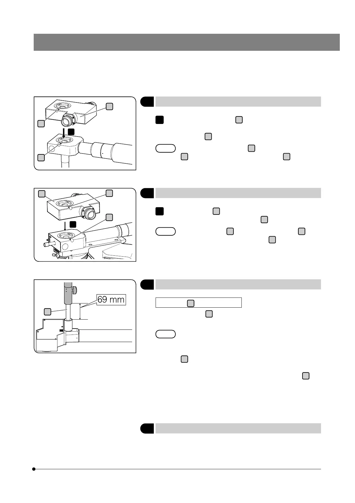
Attach the light path split unit
a
provided with U-MDO10R-3 to the
top of U-MDO10R-3 (at assistant observer position), and tighten the
clamping screw
b
to secure the light path split unit.
Attach the light path split unit
a
so that the clamping screw
b
of U-MDO10R-3 and the clamping screw
c
of the light
path split unit are aligned in one line perpendicularly.
1
4
Attaching U-MDO10B3
6
Attaching U-MDOSV
3
Attaching the light path split unit
a
b
c
1
b
c
a
1
5
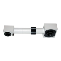
Attaching the stand
Height of the
a
portion of the stand
The height of the
a
portion of the stand to be adjusted after screwing
the stand into U-MDOSV is 69 mm.
If there is a difference in height between the desk top surface
where the microscope frame is installed and the desk top
surface where U-MDOSV is installed, adjust the length of the
a
portion of the stand. For example, if the height difference
is 5 mm (if the desk top surface of the microscope frame is
higher than the desk top surface to install U-MDOSV),
a
will
be 74 mm.
For attaching procedures, see "Attaching the stand" in "5-2 Side by
side observation system for 2 persons and system for 5 persons"
(page 18).
a