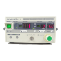
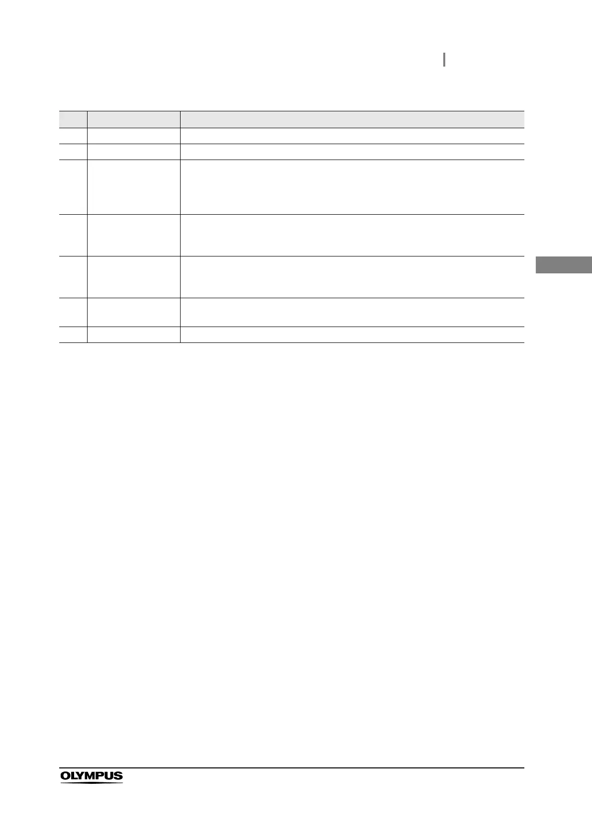
2.2 Front panel
19
UCR INSTRUCTION MANUAL
Ch.2
No. Nomenclature Description
1 Power switch This switch is pressed to turn the endoscopic CO
2
regulation unit ON or OFF.
2 Power indicator Lights up when the endoscopic CO
2
regulation unit is ON.
3 Gas pressure display In the “Cylinder” mode, the gas pressure display indicates the supply pressure level of
the connected CO
2
cylinder. The red LED at the bottom is illuminated when the gas
supply is unavailable due to a drop of the supply pressure. In the “Pipeline” mode, the
top green LED is illuminated.
4 Start/stop switch Press the start/stop switch in the “Stop” mode to light up the start indicator and start
the gas supply. Pressing the switch during gas supply extinguishes the start indicator
and stops the gas flow.
5 Start indicator The indicator blinks when the timer is set to “LONG” or “SHORT”, and illuminates
steadily when the timer is “OFF”. The indicator is not illuminated in the stop mode
regardless of timer ON/OFF.
6 Gas flow indicator The gas flow indicator illuminates green when CO
2
gas is supplied, and is
extinguished when no gas is supplied. The red LED lights give an alarm warning.
7CO
2
gas outlet Connect the gas supply tube or UCR connector of the lens cleaning sheath here.