O.M.A.C. s.r.l.
Via Giovanni Falcone, 8 42048 Rubiera (RE) - Italy Tel.0522/629371 - 629923 Fax 0522/628980
Rev.4 del 01/2011 O.M.A.C. s.r.l.
A) MECHANICAL SAFETY VALVE AND ADJUSTMENT
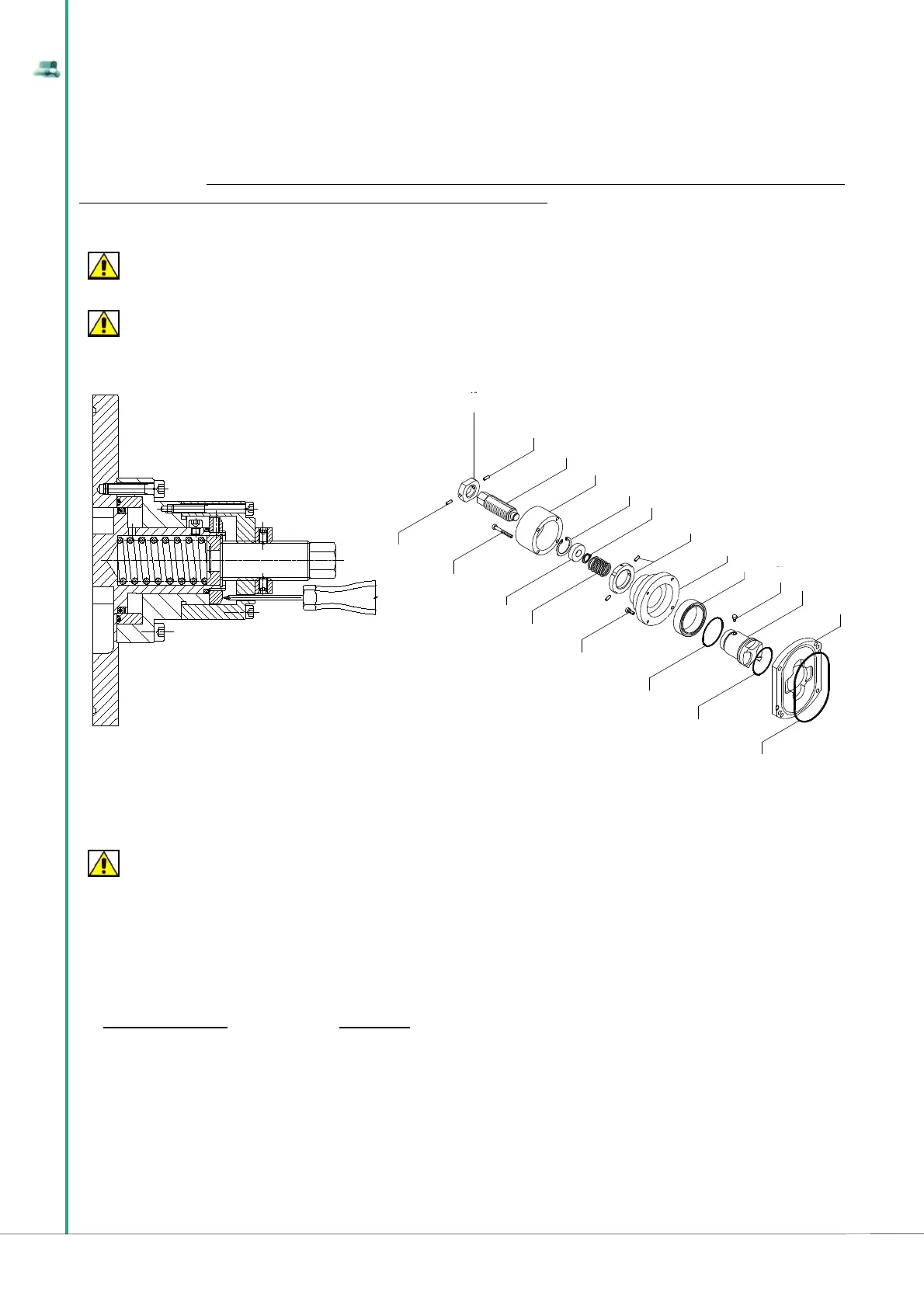
The mechanical safety valve is made up of a cylindrical shaft in which a piston slides, on which a load spring is fi tted.
The mechanical safety valve is fi tted directly onto the front cover of the pump (pump body cover) and its purpose is to intercept pressure peaks of the
fl u id in suction, allowing part of the processed fl uid to recirculate in the pumping chamber.
The adjustment of the safety valve is achieved by adjusting compression of the spring (pos. 71) and on the adjustment screw (pos. 59). The adjustment
of the spring establishes the pressure value at which the mechanical safety valve opens and this adjustment must be carried out on site, as the recycle
entity depends on the pump speed, on the specifi c weight of the fl uid, as well as its viscosity.
To prevent continuous vibrations, the safety valve must be adjusted in such a way that it starts working at a pressure 10% higher than the working
pressure.
ATTENTION
It is recommended to adjust the mechanical safety valve at an opening pressure 10% higher than the LDPU working pressure.
ATTENTION
The adjustment of the mechanical safety valve must be carried out on site by the Customer, since the recycle entity
depends on the LDPU speed, on the specifi c weight of the fl uid, as well as its viscosity.
To adjust the mechanical safety valve one must follow the instructions below:
Completely unscrew the adjustment screw (pos. 59) in order to disable the valve.
Insert a thin rod in the inspection hole on the valve cover, pos. 58, until touching the ring.
Start the LDPU with the safety valve spring loosened, i.e. not under pressure.
Using a screwdriver gradually tighten the adjustment screw (pos. 59 in the fi gure to the right), compressing the spring and checking that the
pressure in the delivery outlet of the LDPU does not exceed the allowed pressure.
ATTENTION
With reference to section 3.3.3, in order to calibrate the spring there must be appropriate manometers on the suction and delivery pipes that indicate the
pressure in
Tighten the adjustment screw until the thin rod starts to move.
Compress the spring by 1/4 screw turn past the critical opening point to prevent vibrations.
Position the regulator retainer (pos. 62 in the fi gure below) and block it with the appropriate hexagon hollow bolt (pos. 65 in the fi gure below).
The mechanical safety valve can also be used in manual mode, to adjust the capacity: unscrew the adjustment screw (pos. 59), release the spring
pressure until moving the piston away (pos. 57) from the pumping chamber, allowing part of the pumped liquid to return into the suction chamber. This
operation is not allowed for volatile fl uids, such as for example solvents and fl uids sensitive to temperature increase, due to continuous recirculation of
the same product. For products viscosity above 15000 cPs, if one must recycle all the pumped liquid it is recommended to install a by-pass on the line,
adequately proportionate, in order to allow the passage of the entire fl ow of the LDPU.
B) PNEUMATIC SAFETY VALVE AND ADJUSTMENT
The pneumatic safety valve is made up of a cylindrical shaft in which a piston slides and it is fi tted directly onto the front cover of the pump (pump body
cover). Its purpose is to intercept pressure peaks of the fl uid in suction, allowing a part of the processed fl uid to recirculate in the pumping chamber. The
safety valve is in contact, on one side, with the processed fl uid, whilst inside it is balanced with the pressure from the pneumatic circuit.
•
•
•
•
•
•
•
62
65
59
66
58
67
61
56
56/1
70
72
57
60
68
45
69
71
63
64
65