7
O.M.A.C. s.r.l.
Via Giovanni Falcone, 8 42048 Rubiera (RE) - Italy Tel.0522/629371 - 629923 Fax 0522/628980
E-mail:info@omacpompe.com SitoWeb:www.omacpompe.com
Rev.4 del 01/2011 O.M.A.C. s.r.l.
Chap.3 - pag.
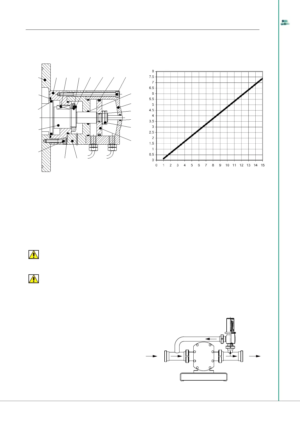
The adjustment of the pneumatic safety valve is carried out on site because it must be connected directly to the compressed air circuit on site. To adjust
it is recommended to use, as reference for the pressure and sizing of the compressed air unit, the graph below showing the correspondence between the
pressure inside the pump and the pressure in the valve. To prevent continuous vibrations, the safety valve must be adjusted in such a way that it starts
working at a pressure 10% higher than the working pressure.
When the force the pneumatic circuit exercises on the valve is higher than that exercised by the fl uid, the valve stays closed; on the contrary the valve is
activated generating discharge volumes that enable balancing of forces, inside the pumping chamber.
Before calibrating the pneumatic safety valve, one must calibrate the pneumatic circuit of the Customer, with a pressure value as follows:
• on the basis of the data carried in the LDPU technical sheet, detect the unit working pressure;
• with this data consult the graph shown on the next page to obtain the pressure value with which the safety valve must be calibrated.
Once one has obtained these values, proceed as indicated below:
• start the “B series lobe displacement Pump Unit” with the safety valve connected to the compressed air circuit;
• with reference to the indications on the manometer on the suction duct in proximity to the LDPU suction inlet, acting on the pneumatic pressure
regulator, manually increase or decrease the pressure value of the pneumatic circuit until reaching the critical balance value, i.e. the value obtained from
the graph.
To prevent continuous vibrations, the safety valve must be adjusted in such a way that it starts working at a pressure 10% higher than the working
pressure.
ATTENTION
The adjustment of the mechanical safety valve must be carried out on site by the Customer, since the recycle entity depends on the LDPU speed, on the
specifi c weight of the fl uid, as well as its viscosity.
ATTENTION
The operations described herein require at least two manometers, for pressure values, installed on the suction and delivery pipes, near the LDPU ope-
nings that connect it to the plant of the Customer.
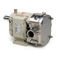
C) EXTERNAL BRIDGE MECHANICAL SAFETY VALVE AND ADJUSTMENT
by-pass pressure / B Series pump correspondence
B Series pump pressure [bar]
by-pass pressure [bar]
91
72
95 98
97
104
93
96
94
92
99
107101
102
103
106
109
108
105
100
The external mechanical safety valve is made up of a spring
valve positioned on a pipe bridge that connects delivery and
suction and can also be used as a by-pass to let all or part of the
processed fl uid fl ow back.
To adjust the external bridge safety valve act on the spring
compression regulation, located on the upper part of the valve
body. The system composed in this manner is one-way so if one
inverts the direction of the LDPU, it is essential to invert the po-
sitioning of the valve as well that, in any case, must always be
on the delivery side.
One can choose various kinds of springs according to the
working pressure. The adjustment must be carried out on site,
acting manually on the special adjustment ring.
SUCTION
DISCHARGE
EXTERNAL BRIDGE
MECHANICAL SAFETY VALVE