O.M.A.C. s.r.l.
Via Giovanni Falcone, 8 42048 Rubiera (RE) - Italy Tel.0522/629371 - 629923 Fax 0522/628980
Rev.4 del 01/2011 O.M.A.C. s.r.l.
ATTENTION
The system composed in this manner is one-way so if one inverts the direction of the pump, it is essential to invert the positioning of the valve as well
that, in any case, must always be on the delivery side.
ATTENTION
The adjustment of the external bridge mechanical safety valve must be carried out on site by the Customer, since the recycle entity depends on the LDPU
speed, on the specifi c weight of the fl uid, as well as its viscosity.
D) MECHANICAL SEALS FLUSHING CIRCUIT
The purpose of fl ushing mechanical seals is generally to cool down and lubricate the sliding faces of the mechanical seal, via forced circulation of a
fl u shing liquid.
The fl ushing liquid and its distribution circuit must be provided by the Customer. The Customer must also check, through his Technical
Offi ce, the compatibility between the fl ushing liquid and the process fl uid, as well as the compatibility between the
fl u shing liquid and the components of the “B series lobe displacement Pump Unit” in close contact (pumping cham-
ber material, seals material, working temperature, etc.)
Once this requirement has been checked and validated, the Tec hnical Offi ce of the Customer will see to expressly authorise the operator responsible for
the installation of the LDPU to fi t the fl ushing circuit on the seals fl ushing chamber and commission it, before starting the LDPU for the fi rst time
ATTENTION
The operator responsible for the fl ushing circuit must be expressly authorised by his Te chnical Offi ce to connect the fl ushing circuit to a system that uses
“fl ushing liquid” compatible with the process fl uid.
O.M.A.C. s.r.l. is not responsible for improper use of the fl ushing liquid nor for damages deriving from contamination of the process fl uid.
DANGER
The improper use of the fl ushing system can cause breakage of mechanical seals resulting in damage to the LDPU
and contamination of the process fl uid. O.M.A.C. s.r.l. is not responsible for improper use of the fl ushing system.
The operator designated by the Customer must connect the fl ushing circuit joints to the input and output holes of the seals fl ushing chambers and adjust
the temperature and pressure according to the type of seal fi tted on the displacement pump, as described below:
- in case of single mechanical seals the fl ushing pressure must be about 1.5 - 2 bar with 0.5 - 1 lt of fl ow-rate;
- in the case of double mechanical seals the fl ushing pressure must be equal to the working pressure or higher by 1 bar, to ensure that the
fi l m created between the sliding faces of the seals is made up of the fl ushing liquid and not by the process fl uid, which according to its chemical compo-
sition may crystallise and solidify after machine down time and generate, upon restarting the unit, a “sticking” phenomenon of the faces, causing their
breakage.
The fl ushing temperature must be established according to the type of processed fl uid and to the fl ushing utility: generally using liquid at room tempera-
ture - about 15° - 20° - is necessary to disperse the heat generated by friction of the seals faces, or vice-versa, using liquid at higher temperatures, for
example 80° - 90°, can be useful for melting, removing, cleaning and lubricating the seals faces.
The dimensions of the inlet and outlet holes joints of the fl ushing circuit are listed in the table in section 1.3.9 in chapter 1.
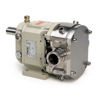
Below there is an illustration of the two kinds of fl ushing:
fl u shing diagram for low pressure seals fl u shing diagram for double seals with circuit under pressure
E) ASEPTIC LIQUID CIRCUIT
The aseptic liquid circuit (water steam), connected to the components of the LDPU which will come into contact with the process fl uid (pump body, unit
connection openings, sealing parts) are used to ensure the product is aseptic, during its transfer cycle performed by the LDPU, from its suction inlet to
its delivery outlet.
•
•