19
O.M.A.C. s.r.l.
Via Giovanni Falcone, 8 42048 Rubiera (RE) - Italy Tel.0522/629371 - 629923 Fax 0522/628980
E-mail:info@omacpompe.com SitoWeb:www.omacpompe.com
Rev.4 del 01/2011 O.M.A.C. s.r.l.
Chap.5 - pag.
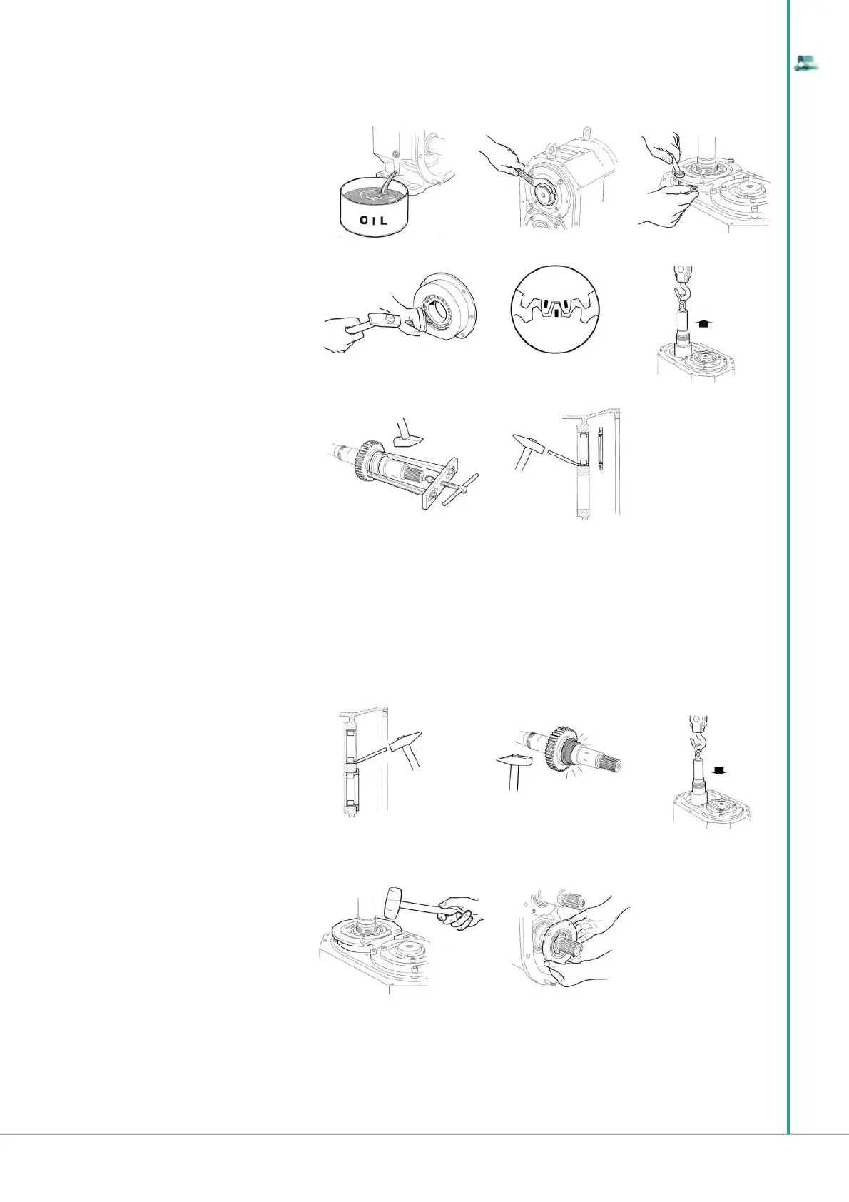
5.9.3 Disassembly of the B550/B660/B680 gear box
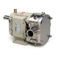
5.9.4 Assembly of the B550/B660/B680 gear box
17 After disassembling the rotor case remove
the oil and the drive key on shaft
18 Remove the gear cover, disconnect the re-
tainer keys of the lock washer and unscrew the
ring nuts
19 Stand the pump upright and extract the two
bearing supports, making use of the threaded
holes for removal.
Doing so you will remove the spacers for axial
adjustement too, which should be marked and
separated for a right re-setting while assembling
20 Remove the ball bearing from its support,
taking away the bull ring
21 Mark the gears in order to set them rightly
while reassembling
22 Withdraw the shafts, with the gears, still inserted. For this operation we suggest a mechanical lifting equipment, which can use the threaded holes
arranged on shaft ends
23 Remove the inside ring of the roller bearing by means of an extractor. Remove the gear taking care not to damage the toothing outline
24 Remove the bearing retainer and extract the outer ring of the roller bearing from the bearing box
17 18 19
20 21 22
23 24
25 Assemble the outer rings of the roller bea-
rings on the bearing housing, using a bearing
retainer to set them axially, because no counter-
boring is arranged.
Assemble the bearing retainer without seal rin-
gs
26 USE GLOVES. The inner ring of the roller
bearing is assembled with a interference, there-
fore we suggest a shrink fi tting, heating the ring
in 90 °C oil bath, in order to avoid any seizure.
Insert the gear keys in their seats with a lightly
forced connection.
IMPORTANT: Assemble the adjustable gear on
the shaft, which will be set up on the pump
27 Assemble the shafts. If the gears heven’t been removed from the shafts, respect the timing previously marked while re-assembling
28 Insert the spacers (10) on the shafts and assemble the supports (75) with the ball bearings already connected. Set the spacers for axial adjustement
(11) and tighten the screws
29 Assemble the seal rings (18) on bearings retainers (9)
25 26 27
28 29