• Measuring process signals
The instrument accepts the measure of process signals
in 4/20 mA and 0/10 Vdc. The instrument provides
excitaon voltage to power up transducers.
• Scaling
The instrument allows to scale the reading to 4 digits (9999 / -1999)
with congurable decimal point to any posion. The ‘second scaling’
funcon can also be used (see secon 1.24).
• Maximum oversignal
‘Maximum oversignal’ is the maximum signal accepted by the in-
strument. Higher signal values may cause instrument damage. Low-
er values are non destrucve but may be out of accuracy specica-
ons.
• Response mes
The response me to a signal step is 300 mSeconds, independent of
the signal range selected.
• Terminal 5 ‘mulfuncon’ - ‘Vexc’ or ‘External control’
To congure the +15 Vdc excitaon voltage at terminal 5, set internal
jumper ‘T’ at posion 1-2 (see secon 1.9). Transducers with a
consumpon of up to 30 mA can be powered from this terminal.
To congure the ‘EK’ external contact funcon at terminal 5, set
internal jumper ‘T’ at posion 4-5 (see secon 1.9). See secon 1.9
for a list of available funcons.
1.16 Process measures
1.17 Measuring frequency
• Start-up, connecons and jumpers
For instrument start-up follow the steps listed at secon 1.7. Signal
connecons are indicated at secon 1.5. Locaon for internal
jumpers is indicated at secon 1.9.
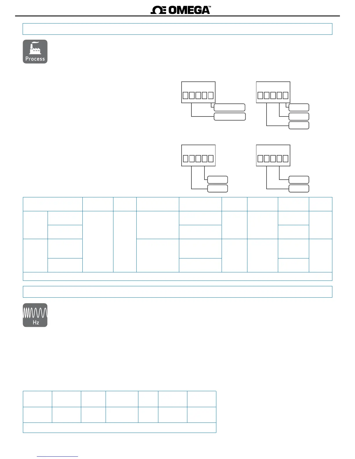
See below a list of typical connecons :
mA +
mA -
12345
• signal 4/20 mA acve
signal (
mA-)
• signal 4/20 mA passive
+15 Vdc (mA+)
12345
+Vdc
common
• signal 0/10 Vdc passive
+15 Vdc
12345
+Vdc
common
• signal 0/10 Vdc acve
12345
• How the instrument measures frequency
The instrument measures frequency from an AC
voltage (Vac) or AC current (Aac) signal. The instrument
detects each ‘0’ crossing of the signal, either ‘0 Vac’
or ‘0 Aac’. All available Vac and Aac signal ranges are
accepted as frequency input signal.
• How to congure the instrument to measure frequency
To measure frequency from a Vac signal, select the internal
jumpers for the desired AC voltage range (see secon 1.9), connect
the signal for the selected voltage range (see secon 1.10), and
congure the instrument to measure frequency (see secon 1.29.1).
The same applies to measure frequency from Aac signals. See
example at secon below.
Ranges
of measure
Scale
by default
Scalable
AC signal
(see secon 1.9)
Jumper
'T'
Response
me
Accuracy
(% reading)
15 to 100Hz 0/100.0 from 9999
to -1999
select Vac or
Aac range
4-5 70mSec. <0.15% of
reading
Table 16 - Ranges of measure for frequency
• Scaling
The default resoluon is 0.1 Hz. The instrument allows to scale the
reading to 4 digits (9999 / -1999) with congurable decimal point
to any posion. The ‘second scaling’ funcon can also be used (see
secon 1.25).
• Maximum and minimum signal
Frequency signals below 15 Hz are measured as ‘0’. Frequency
signals higher than 100 Hz are out of accuracy. Signals higher than
1000 Hz will read ‘display overow’ ‘d.oVr’ error.
Ranges
of measure
Scale
by default
Scalable
Jumper ‘S’
(see secon 1.9)
Jumper ‘T’
(see secon 1.9)
Accuracy
(%FS)
Max.
oversignal
Connecon
(terminals)
Z
in
4/20 mA
passive
(needs Vexc.)
0/100.0
de 9999
a - 1999
D
1-2
<0.15% 25 mA
2 (signal)
5 (Vexc)
4.7 Ohm
acve 4-5
2 (mA+)
4 (mA-)
0/10 Vdc
passive
(needs Vexc.)
A
1-2
<0.20% 25 Vdc
2 (+Vdc)
4 (comm.)
5 (Vexc)
1 M
acve 4-5
2 (+Vdc)
4 (comm.)
Table 15 - Ranges of measure for process signals
• Example
To measure the 50 Hz frequency from a 230 Vac
power line, select jumpers ‘GI’ for 600 Vac signal
range (see secon 1.9), connect signal to terminals
‘1’ and ‘4’ (see secon 1.10), and congure
‘frequency’ at the input signal conguraon menu
(see secon 1.29.1).