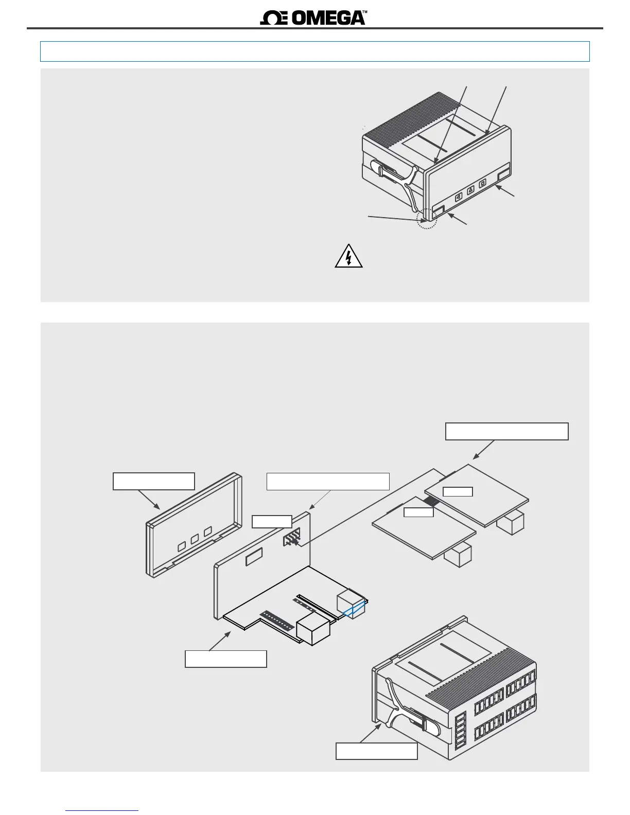
1.26 To open the instrument
To open the housing and access the internal circuits, use a at
screwdriver to unlock clips ‘D’, ‘C’, ‘B’ and ‘A’, in this order. Remove the
front lter. Let the inside of the instrument slide out of the housing.
To reinsert the instrument make sure that all modules are correctly
connected to the pins on the display module. Place all the set into
the housing, assuring that the modules correctly t into the internal
guiding slides of the housing. Once introduced, place again the front
lter at cover ‘X’, and then insert clips ‘A’, ‘B’, ‘C’ and ‘D’, in this order.
* Risk of electric shock. Removing the front cover will grant
access to the internal circuits. Disconnect the power and
the input signal to prevent electric shock to the operator.
Operaon must be performed by qualied personnel only.
The internal structure of the instrument is shown in the graphic
below.
Module ‘Opt.2’ connects to module ‘Opt.1’. Module ‘Opt.1’ connects
to the display. Oponal modules can be replaced, changed, added or
removed simply by placing the proper module at the proper locaon.
See secon 2 for a list of available oponal modules.
Front lter Display
Oponal modules
Housing
Opt.1
Opt.2
Motherboard
Opt.1
X
A
C
B
D