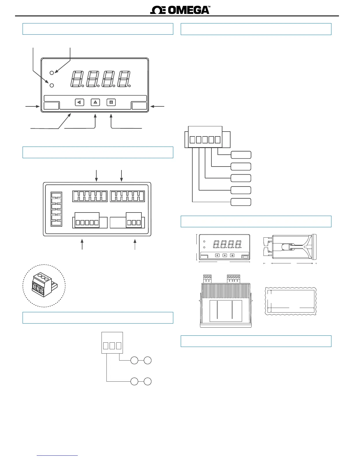
1.2 Front view
1.4 Power connecons
1.5 Signal connecons
Key ‘UP’
Logo
Units
Key ‘SQ’
Key ‘LE’
‘Conguraon menu’
(see secon 1.28)
‘Fast access‘
(see secon 1.28.4)
1.3 Rear view
Signal
(see secon 1.5)
Power
(see secon 1.4)
Alarm 1
Alarm 2
Earth connecon - The
instrument does not need earth
connecon for correct operaon
nor for compliance with security
regulaons. Terminal 9 is not
connected to any internal circuit
and is provided only as a safe
place for earth wire.
Fuse - As requested by security regulaon 61010-1, add a protecon
fuse to the power to act as disconnecon element, easily accessible
to the operator and idened as a protecon device.
250 mA me-lag for power voltage > 50 Vac/dc
400 mA me-lag for power voltage < 50 Vac/dc
~
8 9 0
-
+
~
Power 18 to 265 Vac/dc
Signals up to 600 V and 200 V (AC and DC) must be connected at
terminals 1 and 4. Signals for 5 A current (AC and DC) must be
connected at terminals 3 and 4. All other signals must be connected
between terminals 2 and 4. Terminal 5 is a ‘mulfuncon’ terminal,
congurable with one of the following funcons :
• +15 Vdc excitaon voltage (Vexc) for process signals
• +5 Vdc excitaon for potenometer signals
• connecon for the Pt100 third wire compensaon
• external contact ‘EK’ funcon
To select the terminal 5 funcon, select the posion of internal
jumper ‘T’
(see secon 1.9)
.
1.6 Mechanical dimensions in mm (in)
HV signal
5 A
{
{
~Vac, ±Vdc, resistance, mA, pot,
thermocouple+, Pt+, Ni+, PTC+, NTC+
{
Signal
~600 Vac, ~200 Vac
±600 Vdc, ±200 Vdc
~5 Aac, ±5 Adc
Common
{
neutral, 0 V, common
12345
mulfunc.
{
Vexc, Pt100 3 wire, Pot+,
‘EK’ external control
1. Open the instrument as indicated at secon 1.25 and access
the internal board.
2. Select jumpers ‘S’ for the signal range required (see secon
1.9).
3. Select jumper ‘T’ to assign to mulfuncon terminal 5 the
required funconality (see secon 1.9).
4. Close the instrument ad indicated at secon 1.25.
5. Connect the input signal and the power supply as indicated at
secons 1.4 and 1.5.
6. Enter the ‘conguraon menu’ to congure the instrument
(scaling, alarms, ...) (see secon 1.28).
1.7 Installaon and start-up
Units
Panel
cut-out
96
48
16
8
75
Units
(1.89)
(3.78)
(0.63)
(0.31)(2.95)
44
92
(1.74)
(3.63)
Opon 2 Opon 1
12345 890
Detail of the plug-in screw terminals provided with
the instrument. The instrument is provided with all
terminals needed, both male and female.