Protocol Modbus RTU
Bus type
RS-485, congurable for 9.600 or 4800 bps
Addresses 1 to 247
Formats congurable 8n1, 8e1, 8o1, 8n2
Funcons 4 read register
Registers 0 reading value (16 bits)
1 number of decimals (16 bits)
Errors 0 funcon not supported
1 register not accessible
Isolaon 1000 Vdc
Slots allowed Opt.1
2.3 Module S1 (Modbus RTU)
The S1 module oers 1 Modbus RTU serial output, isolated, to be
installed at slot Opt1.
menu. The instrument must be informed that there is a Modbus RTU
module at slot.1 and this is done at the conguraon menu ‘Tool’ \
‘out.1’ (see secon 1.28.7). Then congure the bus parameters at the
conguraon menu ‘out.1’ \ ‘r485’ (see secon 1.28.8).
The S1 module can be ordered installed in to a Series C instrument
or standalone for later installaon, as it does not require soldering or
special conguraon.
Terminal B B
Terminal A A
Terminal G GND
PowerSignal
Installing, calibrang and conguring a M1 module
If the M1 module has been acquired installed in the instrument, then
the module has been factory calibrated. In this case you can jump
directly to point 7 below.
If the M1 module has been acquired separately and installaon is
needed, follow the next steps :
1. Access the instrument and install the M1 module at slot Opt.1
(see secon 1.25).
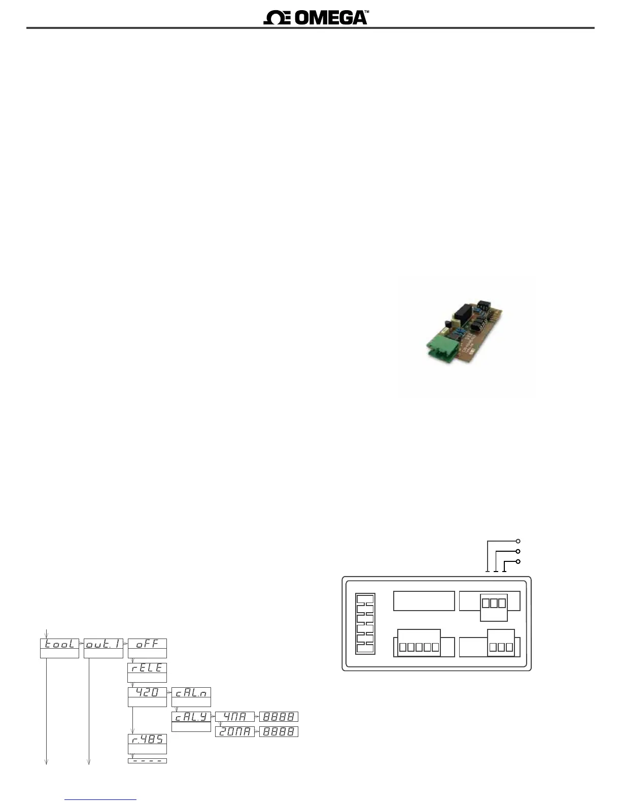
2. From the ‘Conguraon menu’ go to ‘tool’ \ ‘out.1’ and select
value ‘420’ (see secon 1.28.7) to inform the instrument that there
is a M1 analog output module installed.
From this point you will need the calibraon sheet provided together
with the module M1. This sheet shows the values for parameters
‘cAL.y / 4mA’ and ‘cAL.y / 20mA’.
3. When selecng ‘420’ the instrument shows ‘cAL.n’. (‘Do not
calibrate’). Press ‘UP’ (5) to read ‘cAL.y’ (‘Calibrate’).
4. When selecng ‘cAL.y’ (‘Calibrate’) select ‘4 mA’. Display shows
a number. Introduce the value of the ‘cAL.y / 4mA’ indicated at the
calibraon sheet provided together with the M1 module. Increase
the numerical value with key ‘UP’ (5) and reduce the value with
key ‘LE’ (3). Validate the value with key ‘SQ’ (<). See below an
image of the conguraon menu.
5. Repeat with the ‘20 mA’ parameter, and update with the value
‘cAL.y / 20mA’ indicated at the calibraon sheet. Validate with
key ‘SQ’ (<), and press key ‘LE’ (3) several mes to exit the
‘Conguraon menu’.
6. The instrument will reboot when exing the menu. The analog
output is calibrated.
Note : if you do not have the calibraon sheet which was shipped
together with the M1 module, you can use a miliammeter to
measure the mA at the output loop. Then access parameters
‘cAL.y / 4mA’ and ‘cAL.y / 20mA’ and adjust the calibraon value by
checking the miliammeter value.
At this point the module is installed and calibrated. Now congure
the reading associated to the output signal 4 mA and 20 mA.
7. Congure the reading associated to the 4 mA output signal
and the reading associated to the 20 mA output signal, at the
conguraon menu ‘out.1’ \ ‘420’ (see secon 1.28.8).
Do not calibrate
Calibrate
Opon 1
analog output
relay
Disabled
Tools
Modbus RTU
B A G
Opt.1
GND
B
A