5
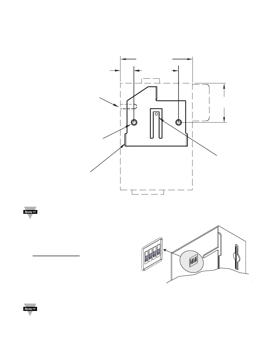
2.2 Wall Mounting
Position unit where required. Mark and drill the two #4 screw holes.
After bracket is mounted on the wall, align back of unit over the three bracket clips, once
engaged, slide downward, the unit will snap in place.
Figure 2.2 Wall Mounting
It is recommended that you ground your unit by connecting a wire to the
Return/Ground position of the relay connector, see Figure 2.8.
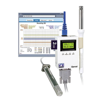
2.3 DIP Switches
The iServer is shipped with all DIP
switches in "OFF" position.
DIP Switch Usage
1) N/C - not used
2) To change to default factory
settings
3) To enable/disable DHCP
4) N/C - not used
To set the iServer to factory default settings, slide DIP switch #2 to ON position.
Power the iServer on and wait about 10 seconds until the iServer fully boots up.
Set the DIP switch #2 back to OFF position (it does not matter if the iServer is
powered ON or OFF, just make sure that the DIP switch is set to OFF, otherwise,
every time the unit is power-cycled the factory settings will take over.
2.42 [61.6]
1.50 [38.1]0.46 [11.7]
1.31 [33.3]
REAR WIRE
ENTRY AREA
DRILL 0.125 [3.17]
USE TWO, #4
FLAT HEAD SCREWS
TO MOUNT BRACKET
BRACKET CLIPS (3)
SNAP
Figure 2.3 DIP Switches