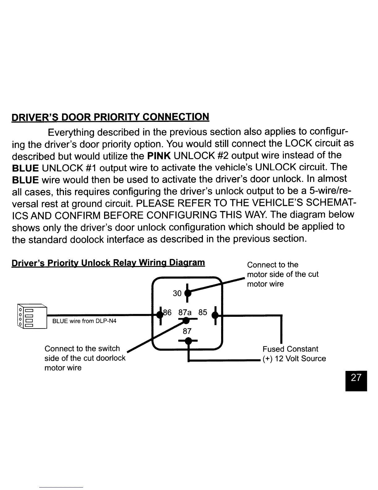
DRIVER'S DOOR PRIORITY CONNECTION
Everything described in the previous section also applies to configur-
ing the driver's door priority option.
You
would still connect the LOCK circuit as
described but would utilize the PINK UNLOCK #2 output wire instead
of
the
BLUE UNLOCK
#1
output wire to activate the vehicle's UNLOCK circuit. The
BLUE wire would then be used to activate the driver's door unlock.
In
almost
all cases, this requires configuring the driver's unlock output to be a 5-wire/re-
versal rest at ground circuit. PLEASE REFER TO THE VEHICLE'S SCHEMAT-
ICS AND CONFIRM BEFORE CONFIGURING THIS
WAY.
The diagram below
shows only the driver's door unlock configuration which should be applied to
the standard doolock interface as described
in
the previous section.
Driver's
Priority
Unlock Relay Wiring Diagram
•
85
Connect to the
motor side
of
the cut
~,.""..~~--
motor wire
Fused Constant
___
-----
(+) 12 Volt Source
30
BLUE wire from DLP-N4
Connect to the switch
side
of
the cut doorlock
motor wire
o c::::J
o
c::J
Oc::J
o c::::J
 Loading...