710.1760.00.04-05 22/05/2014
24
Type
C
CHW 682 to 1202 (Checklist 1)
CHW 1452 to 3652 (Checklist 2)
CHG 225 to 365 (Checklist 1)
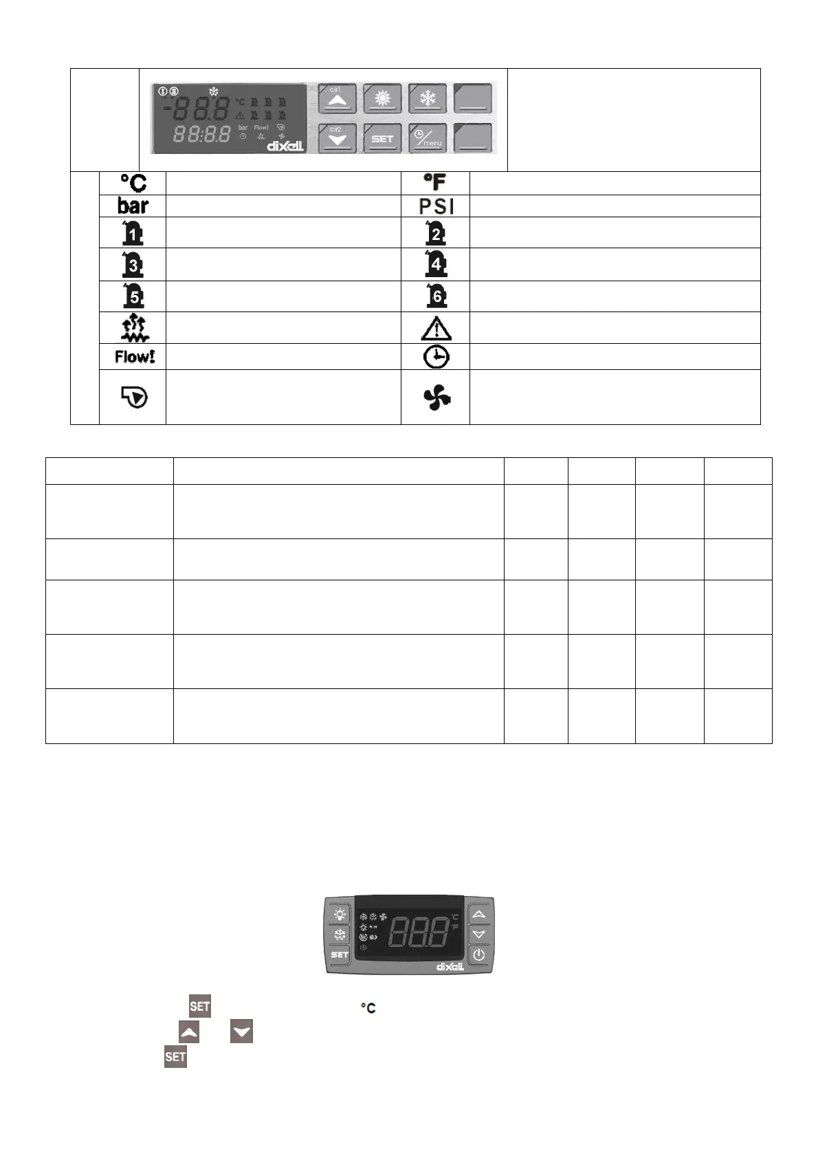
Symbols
degrees Celsius
degrees Fahrenheit
bar
PSI
Compressor 1
Compressor 2
Compressor 3
Compressor 4
Compressor 5
Compressor 6
Antifreeze heating activated
General alarm
Flow alarm
Time display
Water pump: symbol lights up when
water pump is active
Condenser fan: symbol lights up when the digital
output (relay) is configured as a fan ON/OFF or
symbol lights up when the proportional output to
the condenser fan is active.
These delay times are preset for the compressor:
Delay type Description
Controller
Type “A”
Controller
Type “D
Controller
Type “B”
Controller
Type “C”
Delay at start-up
(power ON)
Set a time delay at compressor start-up to graduate the
starting current of the chiller and so that the compressor
is protected against repeated start-ups when there is an
interruption in the power supply.
/ / ~300 ~300
Minimum operating
time
Sets the time that the compressor has to remain in oper-
ation after it has been switched on, even if there is no
further request for this.
/ / ~60 ~60
Minimum switching-
off time
Sets the time that the compressor has to remain out of
operation after it has been switched off, even if there is a
request to switch it on. During this phase the LED for the
compressor flashes.
/ / ~60 ~60
Time interval be-
tween two consecu-
tive ON routines
This sets the minimum switch-off interval between two
consecutive ON routines for the compressor (the maxi-
mum number of ON routines per hour is displayed). Dur-
ing this phase the LED for the compressor flashes.
~360 ~360 / /
Delay in switching on
the compressor after
switching on the
pump
This sets the time between switching on the pump and
switching on the compressor.
/ / ~10 ~10
Please follow the instructions given below for starting up and operating the chiller.
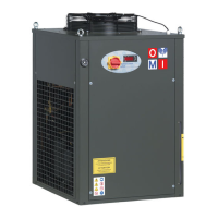
CONTROLLER TYPE “D” (CHW 11 TO CHW 36; CHG 08)
The operating thermostat is supplied in a pre-adjusted state according to the standard specifications of
the chiller listed in the supplement. The operating thermostat controls both the temperature adaptation
functions and the other safety parameters (e.g. alarm management and the running time of the electric
motors). The complete list of parameters in not supplied to the customer because changes in certain pa-
rameters may lead to problems affecting the reliability and characteristics of the chiller.
Instructions for changing the parameters required by the user:
Proceed as follows to change the SET-POINT value:
1. Press the key for 2 seconds (the LED starts to flash).
2. Use the
and arrows to change the SETPOINT.
3. Press or wait 15 sec. (timeout), without pressing any key.