Do you have a question about the Omicron CMA 56 and is the answer not in the manual?
Safety guidelines for operating the CMA 56, handling test leads, and power connections.
Instructions on fuse replacement, operating environment, and handling potential hardware faults.
Verifying delivery of the CMA 56, user manual, and accessories before start-up.
Key operational and safety instructions for the CMA 56 amplifier and its connections.
Step-by-step guide for connecting system components and initiating the CMA 56.
Procedure for connecting the CMA 56, CMC test device, and the test object.
Instructions for controlling amplifiers using CMC software interfaces and AMP-files.
Examples of AMP-file syntax for configuring the CMA 56 with CMC for DOS software.
Description of CMA 56 modules including isolation, signal processing, and monitoring.
Detailed explanation of the CMA 56 block diagram components and their functions.
Automatic hardware self-test on power-up and temperature monitoring with automatic shut-off.
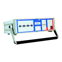
Description of output sockets, LED indicators, and power switch on the front panel.
Detailed description and ordering notes for the 6mm connector used for test object connection.
Information on the socket outlet adapter for using lab cables with the CMA 56.
Information on mains fuse, rear view connections, and CMC test device interface.
Explanation of the "Ampl. in" and "Ampl. out" Lemo sockets for signal input/output.
Manufacturer designation and supplier details for connection plugs and adapters.
Procedure for connecting multiple CMA units in parallel to increase output power.
Configuration for single-phase operation using series circuit 1,2 (L-L) to double output power.
Configuration for single-phase operation using parallel connection 1+2+3 for increased output.
Explanation of LED status indicators for normal operation, overload, temperature, and hardware faults.
Specifications for the mains supply, including voltage, fuse, and frequency.
Detailed specifications for output currents, power, accuracy, and protection features.
Technical data for "Ampl. in" inputs and ambient operating conditions like temperature and humidity.
EMC compliance, safety standards, and physical dimensions of the CMA 56.
Information for ordering accessories, cables, and plugs for the CMA 56.
Contact information for OMICRON electronics GmbH, including address, phone, and email.
| Voltage Gain | 0 to 60 dB |
|---|---|
| Output Impedance | 0.1 Ω |
| Frequency Response | DC ... 1 MHz (-3 dB) |
| Gain Range | 0 to 60 dB |
| Power Supply | 100 ... 240 V, 50/60 Hz |