CP SB1 User Manual
60
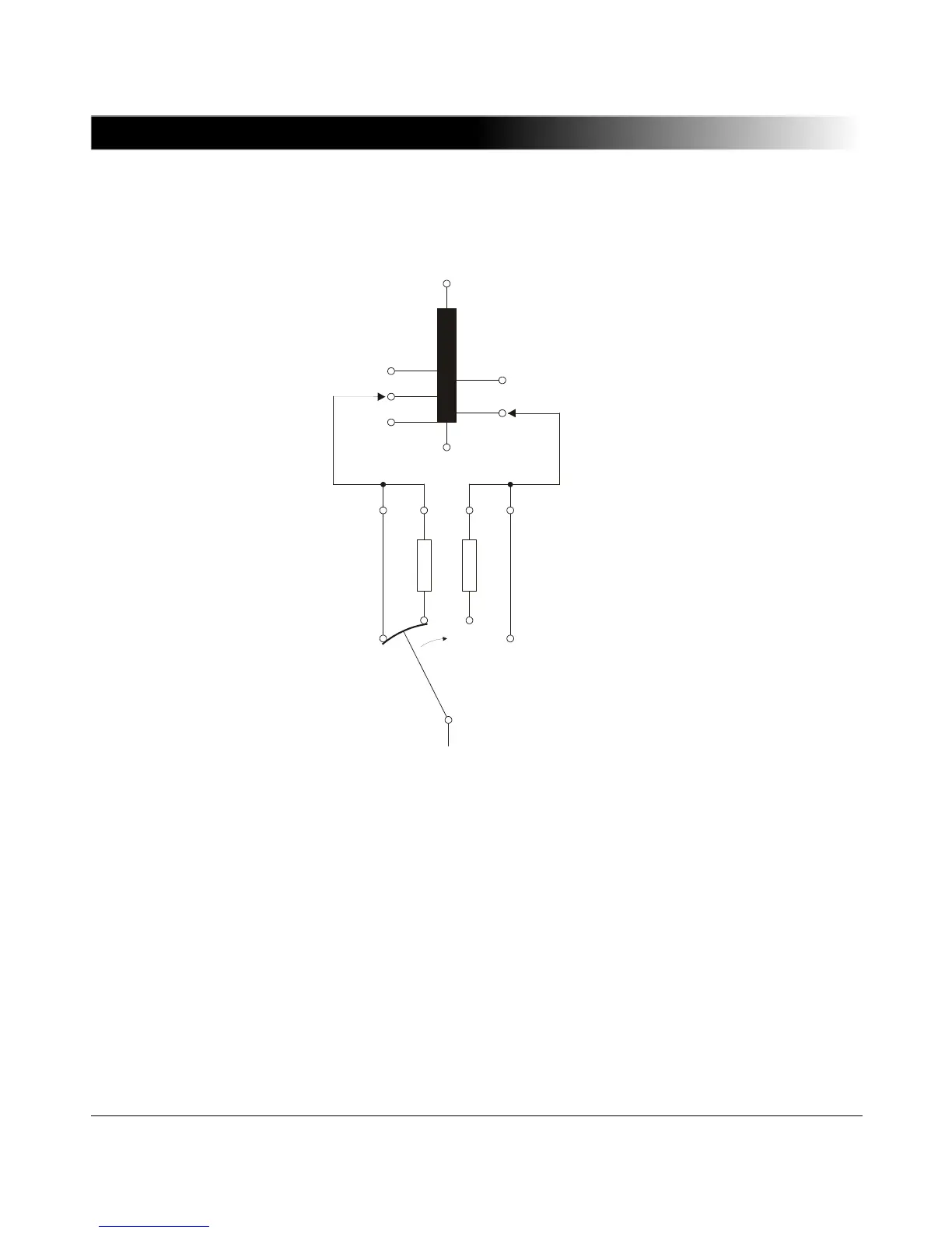
For a better understanding of the resistance measurements, it is necessary to
understand the method of operation of the tap changer (see
Figure 5-4 "Equivalent circuit diagram of On-Load Tap Changer (OLTC)").
Figure 5-4 Equivalent circuit diagram of On-Load Tap Changer (OLTC)
In most cases, the tap changer consists of two units. The first unit is the tap
selector, which is directly located inside the transformer tank and which switches
to the next higher or lower tap without carrying current. The second unit is the
diverter switch, which switches without any interruption from one tap to the next
while carrying load current. The commutation resistances R limit the short circuit
 Loading...