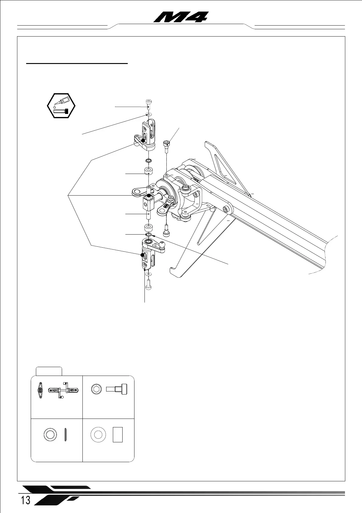
3-2 Tail rotor assembly
M4-302
Tail Blade Grip Set (× 1)
Tail Bellcrank Pin ( × 2)
Tail Blade Grip
Set (× 1)
Tail Bellcrank Pin ( × 2)
Shim
∅ 2x ∅ 4.5x0.2mm ( × 2 )
Socket cap screw
M2x6mm (× 2)
※ Note: Make sure the tail mechanics are easy and smooth to move. If
they aren’t, loosen the six tail case screws, then tighten them crosswise
as indicated above.
13
WWW.OMPHOBBY.COM
Installation steps 安装步骤
※ Note: The round screw head
seat must face outward
Tail Rotor Hub
(× 1)
Tail Rubber
Damper
Shore ( × 2)
Tail Damper
Shim ( × 2)
1
2
4
3
5
6
※ The stepped side of the shim faces
outwards toward the blade grip.
Tail Rubber Damper
80° Shore ( × 2)
Tail Damper Shim ( × 2)