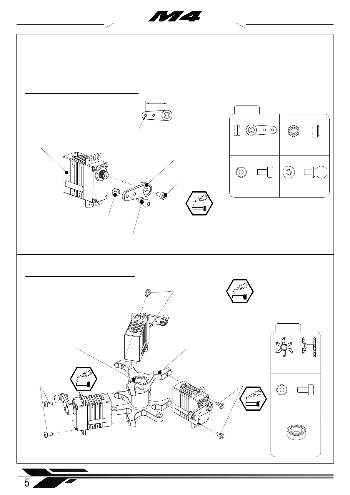
1-1 Cyclic Servo Assembly
Servo Swashplate (× 3)
Servo Arm (× 3)
Socket cap screw
M2x4mm ( × 3)
Ball Joint Screw - L4.65 (× 3)
M2 Nylon locknut (× 3)
Socket cap screw
M2x4mm ( × 2)
Servo Arm (× 3)
Socket cap screw
M2x4mm ( × 3)
Ball Joint Screw - L4.65 (× 3)
M2 Nylon locknut (× 3)
Socket cap screw
M2x4mm ( × 6)
M4-101
M4-102
Servo Rack ( × 1)
Servo Rack ( × 1)
Socket cap screw
M2x4mm ( × 2)
Socket cap screw
M2x4mm ( × 2)
1-2 Servo Rack Assembly
※
The ball joint screw should be screwed
into the outer hole of the servo arm.
16mm
5
WWW.OMPHOBBY.COM
Installation steps 安装步骤
Bearing ∅ 8x ∅ 14x4mm ( × 2)
Bearing ∅ 8x ∅ 14x4mm ( × 2)
※ Note: All servo wires shou ld exit the servo rack in one position , which should be aligned with the rear of the frame .
Partially pre-assembled parts are loosely screwed together without thread locker/glue
Recommendation: Loctite 243 for screws, Loctite 648 for bearing seats.
※ Note: In a crash, the servo arm spline can strip.