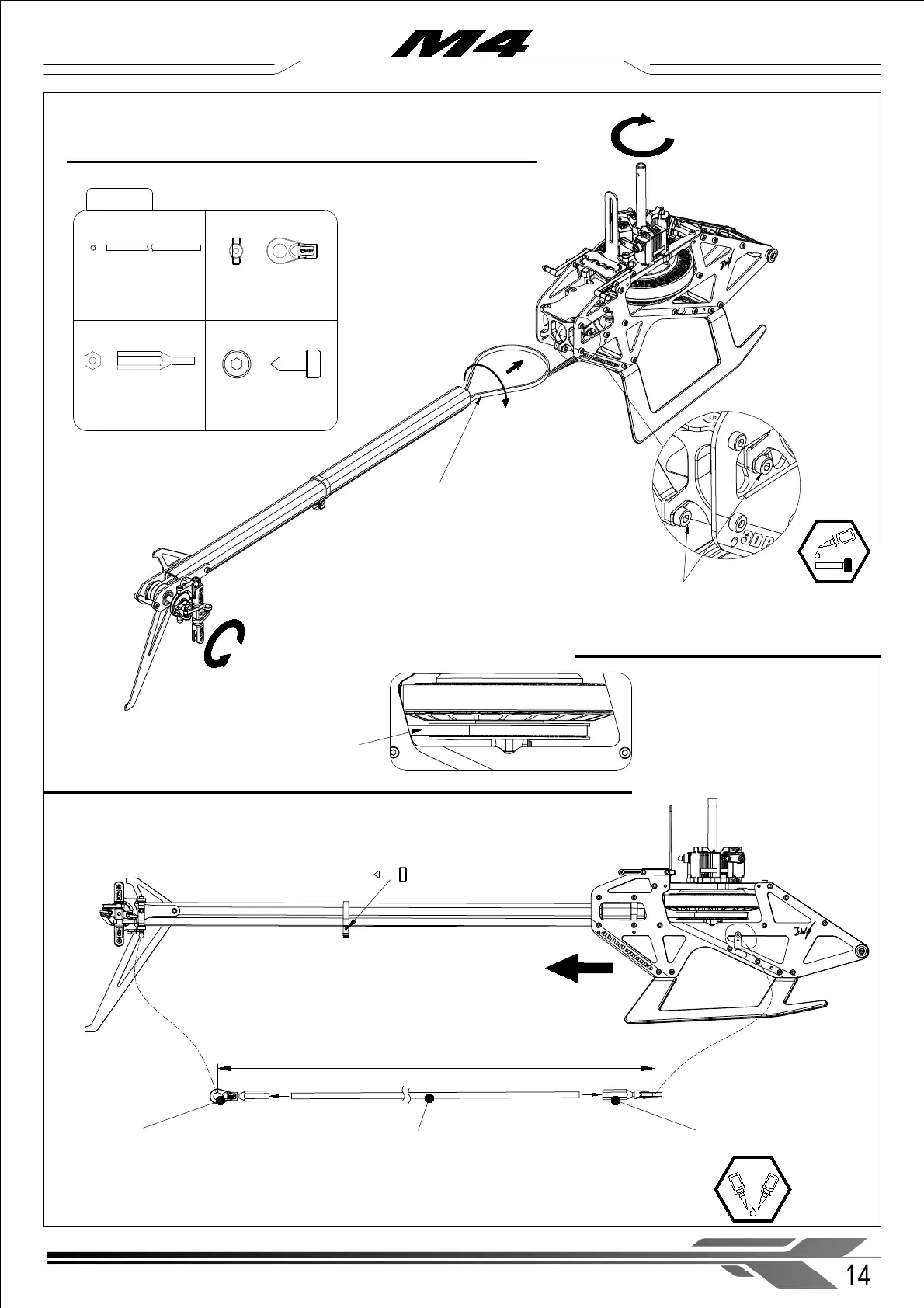
3-3 Tail boom, tail servo linkage rod assembly
※ Pay close attention to the twist direction of
the belt. The belt should be pulled straight
through the boom. Rotate the free end 90° as
shown to achieve proper tail rotor rotation. Do
not twist the belt further than 90° .
The tail boom can be pushed further
inward to give the belt more slack for
installing it onto the main pulley.
Pull the tail boom back to tension the belt to ensure
that flight power is properly transmitted to the tail. Do
not over-tighten the belt, as this can lead to
increased wear and reduced tail drive efficiency.
Center distance approx 544mm
M4-303
Tail servo linkage rod (× 1)
4.5 linkage ball set (× 2)
Control Rod Joint (× 2)
Screw the M2 x 8 self tapping screw to the tail control rod guide after
inserting the control rod into the guide’s slot. Do not over-tighten the screw .
4.5 linkage ball set (× 2) Tail servo linkage rod (× 1) Control Rod Joint (× 2)
※ After the tail belt is tensioned, tighten the
two clamping screws left loose in step 2-2 to
secure the boom in place .
Self-tapping screws
M2x8mm ( × 1)
※ The control rod ends should be sand and glued onto the carbon rod with AB
glue/Epoxy, avoid using Superglue/CA. Pay attention to the correct rod length.
14
WWW.OMPHOBBY.COM
Installation steps 安装步骤
A
B
※ Use sand paper on the rod ends to roughen them and make insertion into the joint easier.