115°
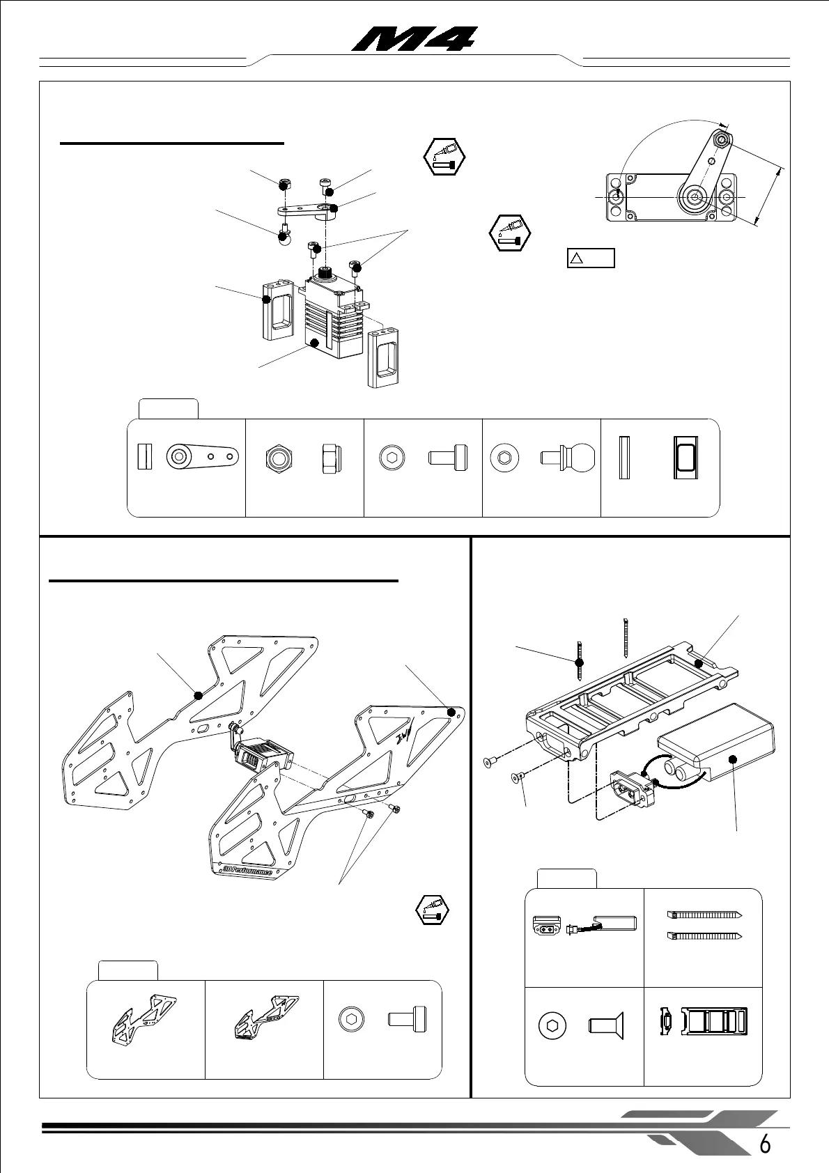
M4-103
Servo Arm (× 1)
M2 Nylon locknut (× 1)
Socket cap screw
M2x4mm ( × 2)
Ball Joint Screw - L4.65 (× 1)
Tail servo mount set (× 2)
2-1 Main frame tail servo assembly
M2 Nylon locknut (× 1)
Tail servo (× 1)
Tail servo mount set (× 2)
Servo Arm (× 1)
Socket cap screw
M2x4mm ( × 2)
Socket cap screw
M2x4mm ( × 1)
Ball Joint Screw - L4.65 (× 1)
Socket cap screw
M2.5x5mm ( × 2)
Main Frame (left) (× 1 )
M4-201
1-3 Tail servo assembly
!
注意
CAUTION
※ The maximum height of the tail servo,
including servo arm, must be less than 40. 0mm.
When the tail servo arm is in the middle position,
the angle relative to the tail servo should be 115°,
as shown above.
6
WWW.OMPHOBBY.COM
Main Frame (right) (× 1 )
Installation steps 安装步骤
Main Frame (left)
(× 1 )
Socket cap screw
M2.5x5mm ( × 2)
Main Frame (right)
(× 1 )
65A ESC (× 1)
65A ESC (× 1)
Strap (× 2)
M4-202
Battery mounting
rail (× 1 )
2-2 Main frame set assembly
Strap (× 2)
Countersunk head
hexagon socket screw
M2 .5 x6mm ( × 2)
Battery mounting rail (× 1 )
countersunk head
hexagon socket screw
M2 .5 x6mm ( × 2)
16mm