B7A
B7A
105
Precautions
Note: The undermentioned is common for all B7A-series Link Terminals.
General
Each
terminal of the B7A-series should be used for only single sig
-
nal
transmission
without a transmission host. The B7A-series can
-
not
be connected to OMRON’
s SYSMAC BUS Remote I/O System.
Avoid
places subject
to corrosive gasses or continual shock and/or
vibration.
If high-level electrostatic discharge is generated at the
installation
site
(e.g., for transfer of a molding material, powder
, or liquid
through
a pipe), separate the Link Terminals as far as possible from the
source
of the electrostatic discharge.
If
the Input and
Output T
erminals are connected via a three-conduc
-
tor cable to transmit signals with a single power supply (i.e., the
power
supply is connected directly to one of the Link T
erminals and
indirectly
to the other), the transmission distance greatly varies with
the
diameter of the cable. This is due to the potential dif
ference be
-
tween
the current on the 0-V transmission wire and on the 0-V I/O
transmission
line
caused by the resistance of the cable. By increas
-
ing
the diameter of the cable (decreasing its resistance), the trans
-
mission distance can be increased. By reducing the resistance of
the
transmission path to 2.5
Ω
or less for example (i.e., increasing
the
thickness of the wire to 1.25 mm
2
or more), a transmission dis
-
tance
of 160 m will be achieved.
It is recommended that a switch for minute loads be connected to
the
16-point screw terminal model because there is a contact input
current
of only 3 to 6
mA to the model from the connected switch or
relay.
The
Output T
erminal has an error of 300 ms maximum after the Out
-
put
T
erminal is turned on. The user should be well aware of this be
-
fore
using error outputs.
Note: The
10-point and 16-point models cannot be connected to
each
other because their transmission signal data formats
are
not compatible.
Screw Terminal Models
Apply
a torque of 0.78 to 1.18 N
S
m to tighten wiring terminals.
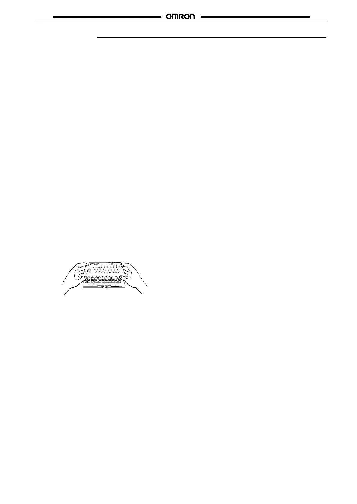
Hold both edges of the terminal cover to open it.
If the Input or Output Terminal is mounted to a panel with screws,
apply
a torque of 0.59 to 0.98 N
S
m to tighten the screws.
Modular Models
Soldering
(with an soldering iron or in a soldering tab) must be com
-
pleted
within 5 s at a temperature of 260
°C or less.
The
supply voltage must be within the operating voltage range. Do
not
use
a power supply which generates irregular voltages or large
ripples.
Do not apply a strong acidic
or alkaline solvent to the printed circuit
board
for removal of the flux. The module of the B7A 10-point model
is
not of closed-mold construction. The solvent must not remain on
the
bottom of the module after the module is cleaned. The module of
the
B7A 16-point model is of closed-mold construction.
The
input and output circuits are not insulated. If
Link T
erminals are
influenced
by external noise, use photocouplers to insulate the I/O
circuits.
Terminals with PLC Connector Models
Apply
a torque of 0.78 to 1.18 N
S
m to tighten wiring terminals.
Be
sure to disconnect the connector unit from the PLC’
s I/O
connec
-
tor
unit when wiring
the screw terminals in order not to impose ex
-
cessive
force on the PLC’
s I/O connector unit.
Use
the B7A in combination
with a PLC correctly
, otherwise the B7A
may
be damaged. The following are correct combinations.
B7A Input Unit and PLC Output Unit
B7A Output Unit and PLC Input Unit
Wiring
Separate
the transmission lines from high
voltage or power lines as
far away as possible and do not wire
the transmission lines in paral
-
lel
with high voltage or power lines. If Link T
erminals are used near a
device
that generates noise, make sure that the Link T
erminals do
not
malfunction due to the noise generated from the device.
Make
sure to turn of
f the Link T
erminals while wiring in order to avoid
a
short-circuiting accident that may damage the internal element(s)
of
the Link T
erminals.
Link
T
erminals will
malfunction if the SIG terminal is short-circuited
with
one of the power terminals or B
jj
terminal. Before turning
the
power on, make sure that the
SIG
terminal is not short-circuited with
these
terminals.
Before
checking the insulation resistance of
the transmission path,
disconnect
the wires from the Link T
erminals.
If
the OUT terminal and positive power terminal of the Output Link
Terminal
is short-circuited during signal transmission, the Link
T
er-
minal
will malfunction. Apply an appropriate load between these ter
-
minals.
When
measuring the current, use a multimeter without disconnect
-
ing
the load.