B7A
B7A
106
Recommended Cables
For B7A with Normal I/O Delay
Cabtire Cable
When
a single
power supply is connected to either the Input T
ermi-
nal
or Output T
erminal:
VCTF 0.75 x 4 C (B7AM)
VCTF 0.75 x 3 C (B7A/S/C)
When
independent power supplies are connected to both Link
T
er-
minals:
VCTF
0.75 x 3 C (B7AM)
VCTF 0.75 x 2 C (B7A/S)
The following cable can also be used.
T
wisted Pair W
ire
When
a single
power supply is connected to either the Input T
ermi-
nal or Output T
erminal, the thickness of the wire must be 0.75 mm
2
or
greater
.
T
ransmission distance: 100 m max.
For B7A with Short I/O Delay
Shielded W
ire
Use a shielded wire with a thickness of 0.75 mm
2
min.
Color
Screw T
erminal Models
Marked “IN” in white
ink. The background is
red.
Input T
erminal
Output T
erminal
Marked “OUT” in black ink.
The background is yellow
.
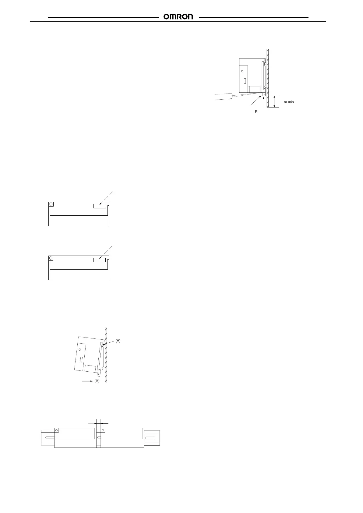
Mounting
To
mount the Input or Output T
erminal to a DIN track, hook the upper
part (part (A) in the illustration) of the Input or Output T
erminal on the
DIN track first. Then press the Input or Output Terminal in the (B)
direction.
(A)
(B)
When mounting more than two Input or Output Terminals side by
side,
leave a space of 3 mm minimum between each T
erminal.
It
is recommended that PFP-S Spacers be used to secure a space
of
3 mm between each Input or Output T
erminal.
3mm min.
Insert a flat-blade screwdriver to part (C) to dismount the Input or
Output
T
erminal from a DIN track.
(C)
30mm min.
Rail stopper