B7AM-8j
B7AM-8j
60
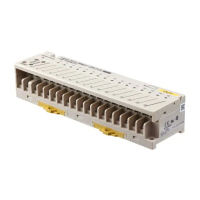
Nomenclature
Power terminals
T
ransmission terminals
Output terminals
Power
terminals
Input
transmission path
Input terminals
Input indicators
Functions
Output indicators
Power supply/
error indicator
Indicator Operation
Indicator Function
POWER/ERR G Lit
when power is supplied and the
T
erminal is operating without error
.
R
Lit during transmission errors
(SIG2).
N
Not lit when power is not supplied.
I/O O
Lit when the input signals are ON.
N
Not lit when the signals are OFF
.
Note:
G: Green indicator lit; R: Red indicator lit;
O: Orange indicator lit; N: Not lit
Recommended Solderless Terminals
Wire JIS
specifications
0.75 mm
2
(AWG#18)
RA
V 1.25 to 3.5 (vinyl-insulated round
1.25 mm
2
(AWG#16)
wire
or RAP 1.25 to 3.5
(nylon-insulated round wire)
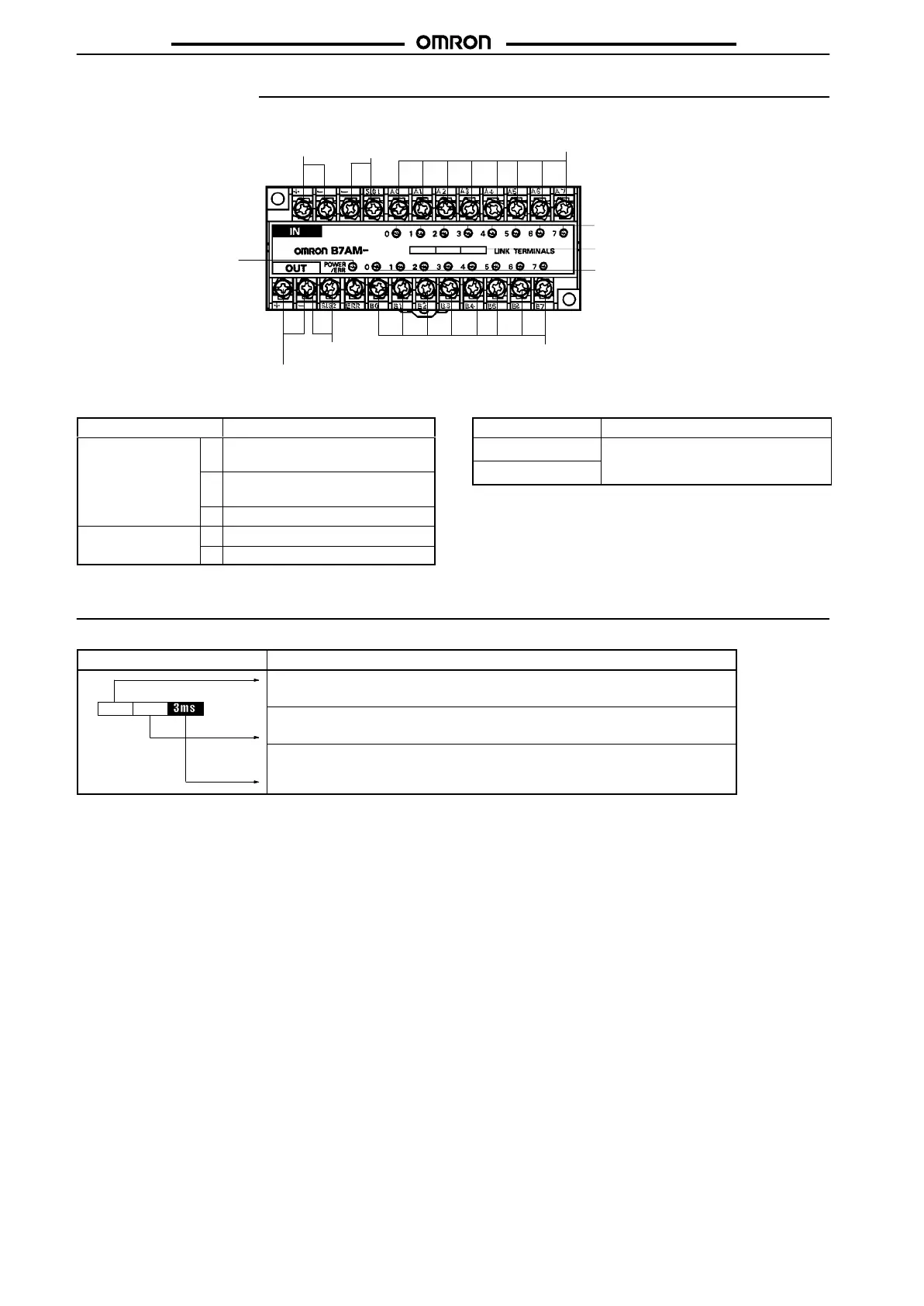
Functions
Display Description
I/O configuration
Indicates the compatible transistor type.
0.1ANPN
Output current
Indicates the rated output current value of the B7A per point.
I/O delay time
Indicates the typical I/O delay time of the B7A. Use a combination of an Input and
Output Link T
erminal with the same I/O delay time.