B7A
B7A
90
10 11 12 13 14 15 16 17 18
IN07
IN08
IN09
NC
NC
NC
NC
SIG
+
10 11 12 13 14 15 16 17 18
I
NC
IN06
IN05
IN04
IN03
IN02
IN01
IN00
9
8
7
6 5 4
3 2 1
10 11 12 13 14 15 16 17 18
OUT07
OUT08
OUT09
NC
N/P
EPR
SIG
NC
+
10 11 12 13 14 15 16 17 18
I
NC
OUT06
OUT05
OUT04
OUT03
OUT02
OUT01
OUT00
9 8 7 6 5 4 3 2 1
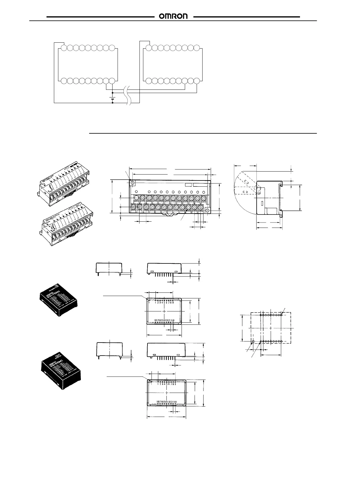
Transmission
distance
100 m max.
Input T
erminal
Output T
erminal
12 to 24 VDC
Connection
of Single Power Supply to Input or Output T
erminal
Note: In this example, a VCTF transmission
cable
with a
thickness of 0.75 mm
2
min.
is
used, through which a current of 1.2 A
max.
can be transmitted.
Dimensions
Note:
All units are in millimeters unless otherwise indicated.
113.5
105
9.5
7.1
8.5
4
37
4.25
12.5
8
45
32
35
4.9
35.3
(32.2)
(14)
P2
Two, 4.5 dia.
mounting
screws
Twenty-three,
M3.5 terminal
screws
4
Screw Terminal Models
Modular Models
B7A-T10M2 (Input)
Mounting Holes
(T
op V
iew)
40
3025.4
3.5
7.62
11
0.5
1.6
Positioning pin 1.4 dia.
2.54±0.05
20.32±0.1
25.4
2.54±0.05
2.54 x 8 = 20.32±0.1
Eighteen, 1.1 dia holes
Pin No.1
7.62
1.8 dia. hole min.
0.64 x
0.64
+0.1
0
45
25.4
30
3.5
16
0.5
1.6
7.62
2.54±0.05
20.32±0.1
Positioning pin 1.4 dia.
B7A-R10MC (Output)
0.64
x
0.64