B7A
B7A
93
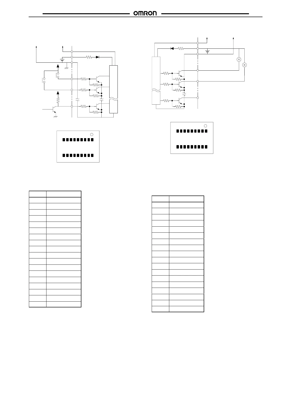
Modular Models
Internal circuit
Transmission
line
SIG
12 to 24 VDC
+
–
5 VDC
5 VDC
B7A-T10M2
(Input, Active High for TTL)
9 8 7 6 5 4 3 2 1
1011 12131415161718
T
op V
iew
Note: Do not short-circuit the SIG terminal with the positive
power supply terminal, negative power supply terminal,
otherwise the internal elements of the B7A will be dam-
aged
and no transmission will be possible.
INjj
INjj
INjj
No. Terminal
1 IN00
2 IN01
3 IN02
4 IN03
5 IN04
6 IN05
7 IN06
8 NC
9 –
10 IN07
11 IN08
12 IN09
13 NC
14 NC
15 NC
16 NC
17 SIG
18 +
B7A-R10MC (Output, NPN Open Collector)
9 8 7 6 5 4 3 2 1
1011 12131415161718
SIG
+
–
Transmission
line
12 to 24 VDC
Internal circuit
Top
V
iew
Note:
Do not short-circuit any out
-
put A terminal with the cor
-
responding B terminal,
otherwise the internal ele
-
ments of the B7A will be
damaged.
ERR
OUTjj
OUTjj
Relay
No. Terminal
1 OUT00
2 OUT01
3 OUT02
4 OUT03
5 OUT04
6 OUT05
7 OUT06
8 NC
9 –
10 OUT07
11 OUT08
12 OUT09
13 NC
14 N/P
15 ERR
16 SIG
17 NC
18 +