7. Using the UPS monitoring software and contact signal
51
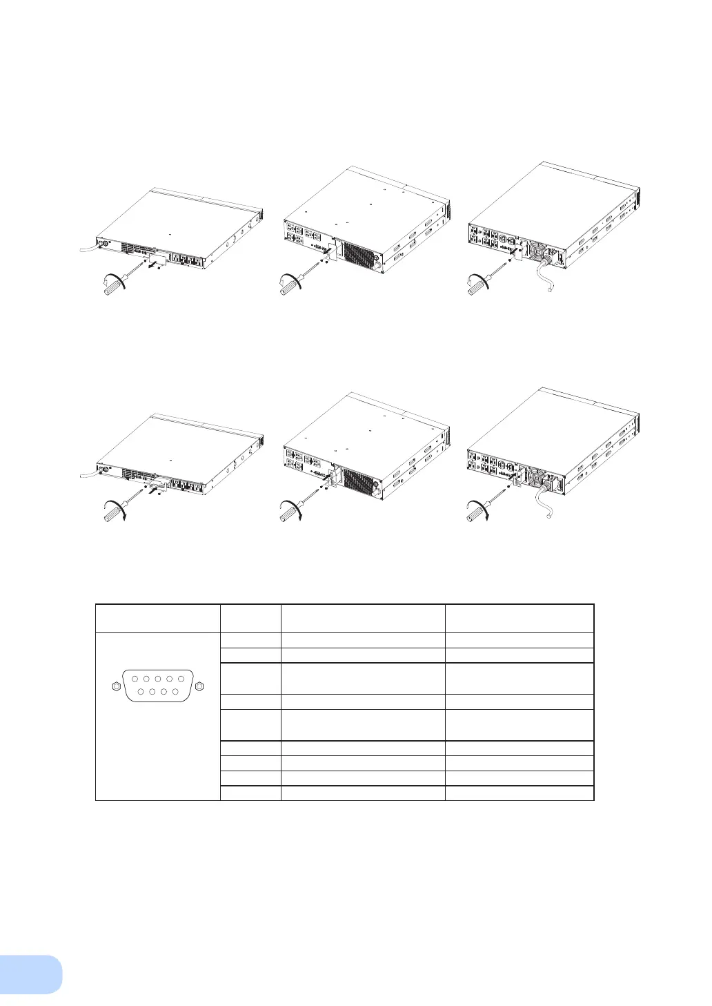
7-4-4. Contact Signal Connector (female DSUB9P)
● Insert method of contact signal card
(1) Remove the two screws below the signal card expansion slot on the back of the unit, and re-
move the cover.
Pin assignment
Pin number
For jumper setting “SC07”
* Factory settings
For jumper setting “SC05/06”
1 Battery LOW signal output (BL) NC
2 Trouble signal output (TR) Backup signal output (BU)
3 Backup stop signal input (BS)
Backup reverse signal output
(
N
BU)
4 NC COMMON (COM)
5 COMMON (COM)
Battery Low Signal output
(BL)
Front view
Screw size: inch screw
#4-40 UNC
6 Remote ON/OFF input (-) Backup stop signal input (BS)
7 Remote ON/OFF input (+) Remote ON/OFF input (-)
8 Backup signal output (BU) Trouble Signal output (TR)
9
Deteriorated battery signal output (WB)
Remote ON/OFF input (+)
<BN75R> <BN150R> <BN300R>
(2) Carefully insert the contact signal card whose settings have been changed, and securely
tighten the 2 screws.
<BN75R> <BN150R> <BN300R>
 Loading...


