162
Programming Devices Section 3-3
3-3-4 Peripheral Port Specifications
Protocol PLC Setup and DIP Switch Settings
3-3-5 RS-232C Port Specifications
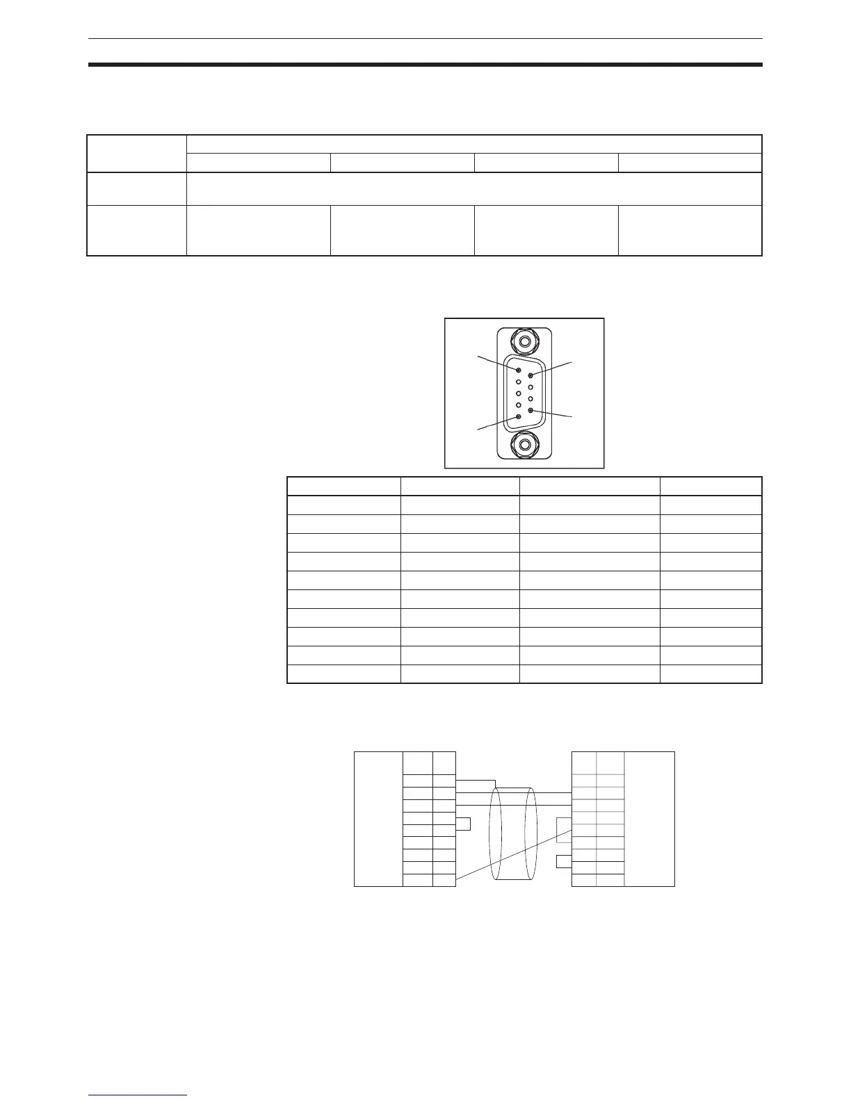
Connector Pin Arrangement
Connection between CJ-series CPU Unit and Personal Computer
The following connections are in Host Link serial communications mode.
Pin No. 4 Peripheral port settings (in PLC Setup)
Default value: 0 hex NT Link: 2 hex Peripheral bus: 4 hex Host Link: 5 hex
OFF Programming Console or other CX-Programmer through peripheral bus (automatically detects the Pro-
gramming Device’s communications parameters)
ON Host computer or CX-
Programmer
(Host Link)
PT
(NT Link))
CX-Programmer
(Peripheral bus)
Host computer or CX-
Programmer
(Host Link)
Pin No. Signal Name Direction
1 FG Protection earth ---
2 SD (TXD) Send data Output
3 RD (RXD) Receive data Input
4 RS (RTS) Request to send Output
5 CS (CTS) Clear to send Input
6 5 V Power supply ---
7 DR (DSR) Data set ready Input
8 ER (DTR) Data terminal ready Output
9 SG (0 V) Signal ground ---
Connector hood FG Protection earth ---
1
5
6
9
1
2
3
4
5
6
7
8
9
CD
RD
SD
ER
SG
DR
RS
CS
CI
1
2
3
4
5
6
7
8
9
FG
SD
RD
RS
CS
5V
DR
ER
SG
Personal computer
RS-232C
interface
CPU Unit
D-SUB
, 9-pin connector
Female connector on cable
D-sub, 9-pin connector
Male connector on cable
RS-232C
interface
Signal Pin
No.
Pin
No.
Signal
 Loading...


