293
PLC Setup Section 7-1
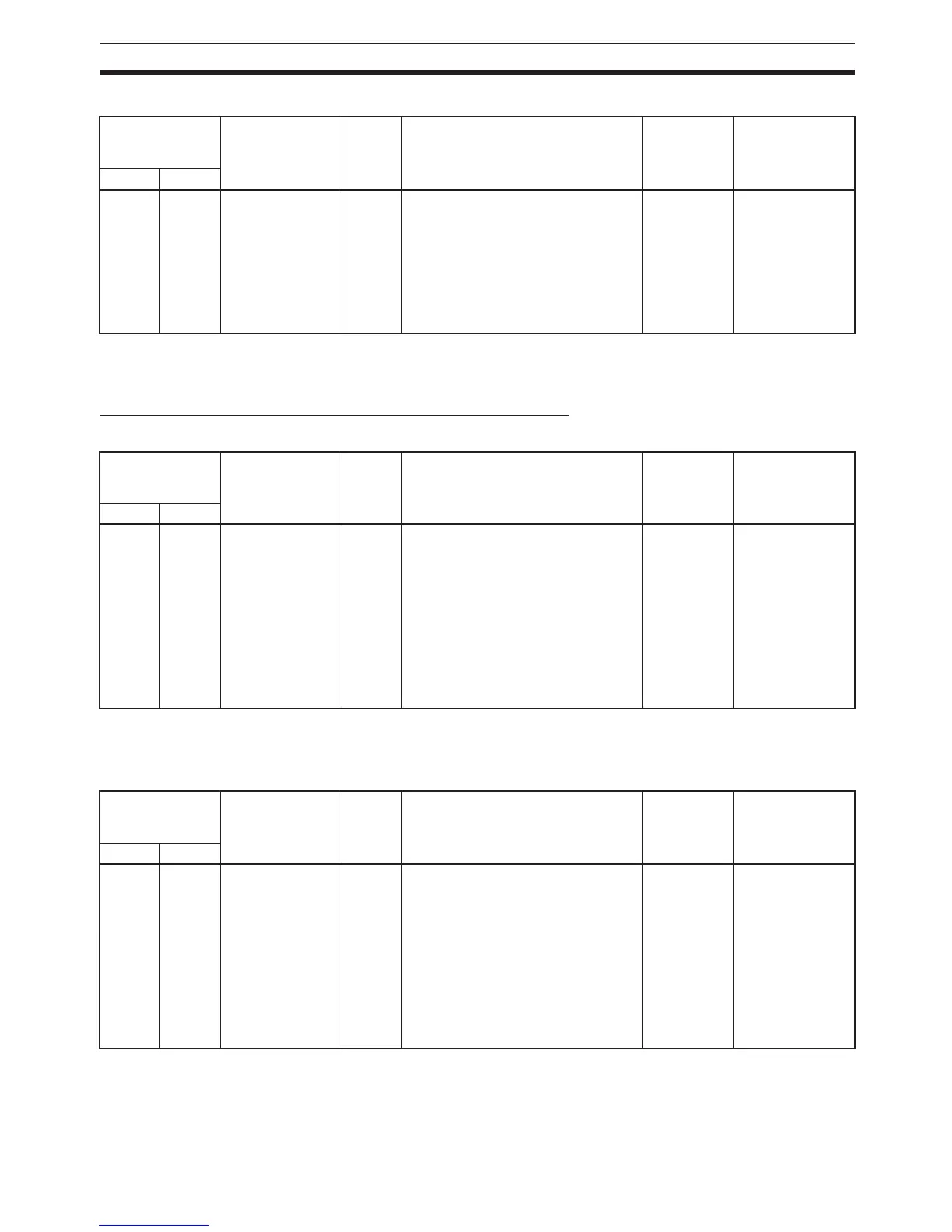
High-speed Counter 1 Pulse Input Setting (Pulse Input Mode)
Note When the CX-Programmer is being used to make the setting, the setting is
input in decimal.
Input Operation Settings for Built-in Inputs IN0 to IN3
Input Operation Setting for IN0
Note When IN0 is set as an interrupt input (1 hex), use the MSKS(690) instruction
to select direct mode or counter mode operation.
Input Operation Setting for IN1
Note When IN1 is set as an interrupt input (1 hex), use the MSKS(690) instruction
to select direct mode or counter mode operation.
Programming
Console setting
address
Settings Default Function Related
Auxiliary
Area flags/
bits
Time when
setting is read
by CPU Unit
Word Bits
53 00 to 03 0 hex: Differential
phase inputs
1 hex: Pulse +
direction inputs
2 hex: Up/Down
inputs
3 hex: Increment
pulse input
0 hex Specifies the pulse-input method for
high-speed counter 1.
--- When power is
turned ON
Programming
Console setting
address
Settings Default Function Related
Auxiliary
Area flags/
bits
Time when
setting is read
by CPU Unit
Word Bits
60 00 to 03 0 hex:
Normal (General-
purpose input)
1 hex:
Interrupt (Inter-
rupt input) (See
note.)
2 hex:
Quick (Quick-
response input)
0 hex Specifies the kind of input that is
being received at built-in input IN0.
--- When power is
turned ON
Programming
Console setting
address
Settings Default Function Related
Auxiliary
Area flags/
bits
Time when
setting i
s read
by CPU Unit
Word Bits
60 04 to 07 0 hex:
Normal (General-
purpose input)
1 hex:
Interrupt (Inter-
rupt input) (See
note.)
2 hex:
Quick (Quick-
response input)
0 hex Specifies the kind of input that is
being received at built-in input IN1.
--- When power is
turned ON
 Loading...


