294
PLC Setup Section 7-1
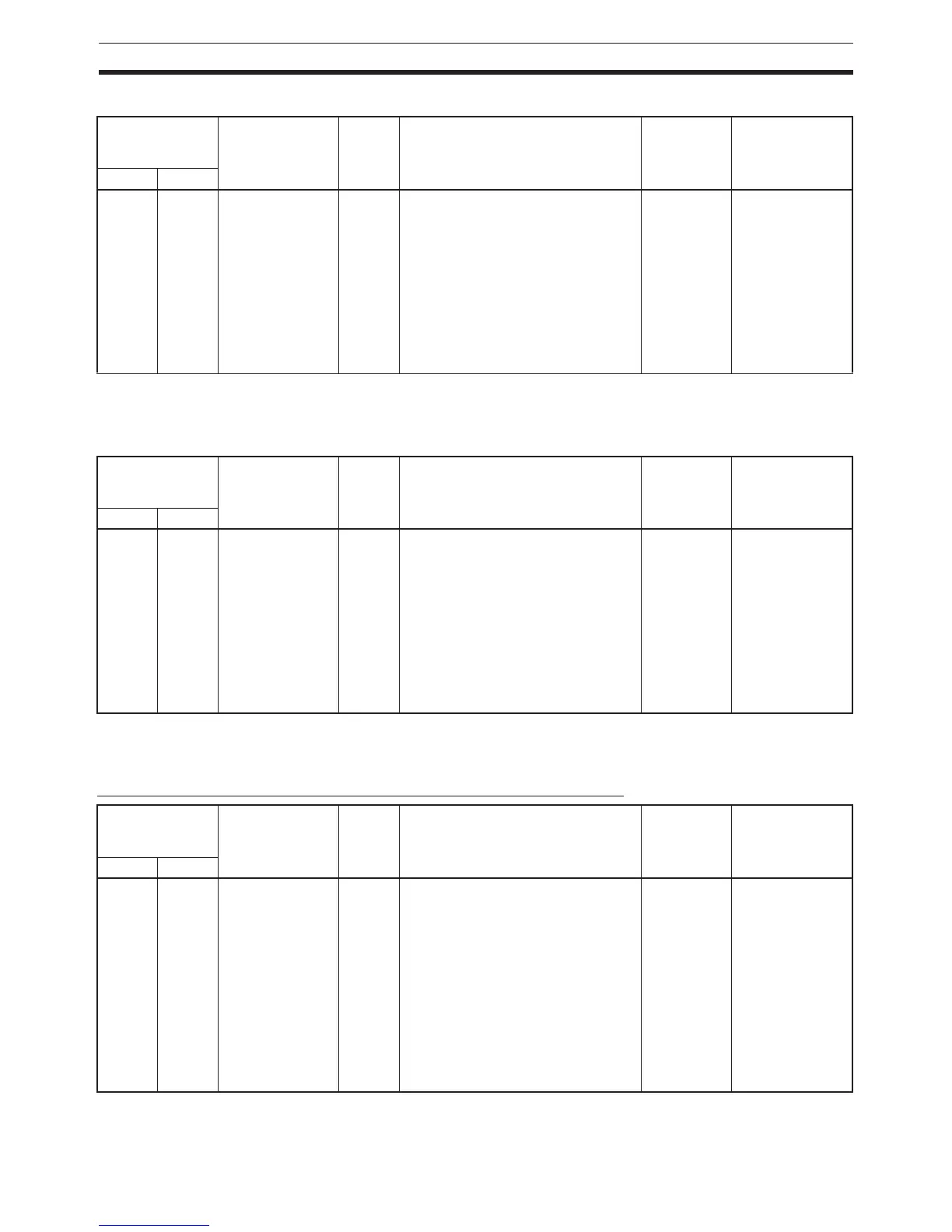
Input Operation Setting for IN2
Note When IN2 is set as an interrupt input (1 hex), use the MSKS(690) instruction
to select direct mode or counter mode operation.
Input Operation Setting for IN3
Note When IN3 is set as an interrupt input (1 hex), use the MSKS(690) instruction
to select direct mode or counter mode operation.
Input Time Constant Setting for the General-purpose Inputs
Programming
Console setting
address
Settings Default Function Related
Auxiliary
Area flags/
bits
Time when
setting is read
by CPU Unit
Word Bits
60 08 to 11 0 hex:
Normal (General-
purpose input)
1 hex:
Interrupt (Inter-
rupt input) (See
note.)
2 hex:
Quick (Quick-
response input)
0 hex Specifies the kind of input that is
being received at built-in input IN2.
Note The input operation setting for
IN2 is disabled when high-
speed counter 1 is being used
and the reset method is set to
Phase-Z signal + software
reset.
--- When power is
turned ON
Programming
Console setting
address
Settings Default Function Related
Auxiliary
Area flags/
bits
Time when
setting is read
by CPU Unit
Word Bits
60 12 to 15 0 hex:
Normal (General-
purpose input)
1 hex:
Interrupt (Inter-
rupt input) (See
note.)
2 hex:
Quick (Quick-
response input)
0 hex Specifies the kind of input that is
being received at built-in input IN3
Note The input operation setting for
IN3 is disabled when high-
speed counter 0 is being used
and the reset method is set to
Phase-Z signal + software
reset.
--- When power is
turned ON
Programming
Console setting
address
Setting
s Default Function Related
Auxiliary
Area flags/
bits
Time when
setting is read
by CPU Unit
Word Bits
61 00 to 07 00 hex: Default
(8 ms)
10 hex: 0 ms
(no filter)
11 hex: 0.5 ms
12 hex: 1 ms
13 hex: 2 ms
14 hex: 4 ms
15 hex: 8 ms
16 hex: 16 ms
17 hex: 32 ms
0 hex Specifies the input time constant for
general-purpose inputs IN0 to IN9.
Note This setting has no effect on
inputs set as interrupt inputs,
quick-response inputs, or
high-speed counters.
--- When operation
starts
 Loading...


