125
SECTION 4
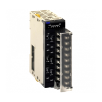
CS-series Analog Output Units
This section explains how to use the CS1W-DA041/08V/08C Analog Output Units.
4-1 Specifications . . . . . . . . . . . . . . . . . . . . . . . . . . . . . . . . . . . . . . . . . . . . . . . . . 126
4-1-1 Specifications . . . . . . . . . . . . . . . . . . . . . . . . . . . . . . . . . . . . . . . . . . 126
4-1-2 Output Function Block Diagram . . . . . . . . . . . . . . . . . . . . . . . . . . . 128
4-1-3 Output Specifications . . . . . . . . . . . . . . . . . . . . . . . . . . . . . . . . . . . . 128
4-2 Operating Procedure . . . . . . . . . . . . . . . . . . . . . . . . . . . . . . . . . . . . . . . . . . . . 130
4-2-1 Procedure Examples . . . . . . . . . . . . . . . . . . . . . . . . . . . . . . . . . . . . . 131
4-3 Components and Switch Settings . . . . . . . . . . . . . . . . . . . . . . . . . . . . . . . . . . 136
4-3-1 Indicators . . . . . . . . . . . . . . . . . . . . . . . . . . . . . . . . . . . . . . . . . . . . . 137
4-3-2 Unit Number Switch. . . . . . . . . . . . . . . . . . . . . . . . . . . . . . . . . . . . . 138
4-3-3 Operation Mode Switch . . . . . . . . . . . . . . . . . . . . . . . . . . . . . . . . . . 138
4-4 Wiring . . . . . . . . . . . . . . . . . . . . . . . . . . . . . . . . . . . . . . . . . . . . . . . . . . . . . . . 139
4-4-1 Terminal Arrangement . . . . . . . . . . . . . . . . . . . . . . . . . . . . . . . . . . . 139
4-4-2 Internal Circuitry . . . . . . . . . . . . . . . . . . . . . . . . . . . . . . . . . . . . . . . 140
4-4-3 Output Wiring Example . . . . . . . . . . . . . . . . . . . . . . . . . . . . . . . . . . 141
4-4-4 Output Wiring Considerations . . . . . . . . . . . . . . . . . . . . . . . . . . . . . 142
4-5 Exchanging Data with the CPU Unit . . . . . . . . . . . . . . . . . . . . . . . . . . . . . . . 142
4-5-1 Outline of Data Exchange. . . . . . . . . . . . . . . . . . . . . . . . . . . . . . . . . 142
4-5-2 Unit Number Settings . . . . . . . . . . . . . . . . . . . . . . . . . . . . . . . . . . . . 143
4-5-3 Special I/O Unit Restart Bits . . . . . . . . . . . . . . . . . . . . . . . . . . . . . . 143
4-5-4 Fixed Data Allocations . . . . . . . . . . . . . . . . . . . . . . . . . . . . . . . . . . . 144
4-5-5 I/O Refresh Data Allocations . . . . . . . . . . . . . . . . . . . . . . . . . . . . . . 146
4-6 Analog Output Functions and Operating Procedures . . . . . . . . . . . . . . . . . . . 149
4-6-1 Output Settings and Conversions . . . . . . . . . . . . . . . . . . . . . . . . . . . 149
4-6-2 Starting and Stopping Conversion . . . . . . . . . . . . . . . . . . . . . . . . . . 151
4-6-3 Output Hold Function. . . . . . . . . . . . . . . . . . . . . . . . . . . . . . . . . . . . 152
4-6-4 Output Setting Errors . . . . . . . . . . . . . . . . . . . . . . . . . . . . . . . . . . . . 153
4-7 Adjusting Offset and Gain . . . . . . . . . . . . . . . . . . . . . . . . . . . . . . . . . . . . . . . 153
4-7-1 Adjustment Mode Operational Flow . . . . . . . . . . . . . . . . . . . . . . . . 153
4-7-2 Output Offset and Gain Adjustment Procedures . . . . . . . . . . . . . . . 155
4-8 Handling Errors and Alarms . . . . . . . . . . . . . . . . . . . . . . . . . . . . . . . . . . . . . . 163
4-8-1 Indicators and Error Flowchart. . . . . . . . . . . . . . . . . . . . . . . . . . . . . 163
4-8-2 Alarms Occurring at the Analog Output Unit. . . . . . . . . . . . . . . . . . 164
4-8-3 Errors in the CPU Unit . . . . . . . . . . . . . . . . . . . . . . . . . . . . . . . . . . . 165
4-8-4 Restarting Special I/O Units . . . . . . . . . . . . . . . . . . . . . . . . . . . . . . . 166
4-8-5 Troubleshooting . . . . . . . . . . . . . . . . . . . . . . . . . . . . . . . . . . . . . . . . 167