288
Specifications Section 7-1
7-1 Specifications
7-1-1 Specifications
Note 1. Refer to Appendix A Dimensions on page 359 for details on the Unit’s di-
mensions.
2. The maximum number of Analog I/O Units that can be mounted to one
Rack will varies depending on the Power Supply Unit model and the cur-
rent consumption of the other Units mounted to the Rack.
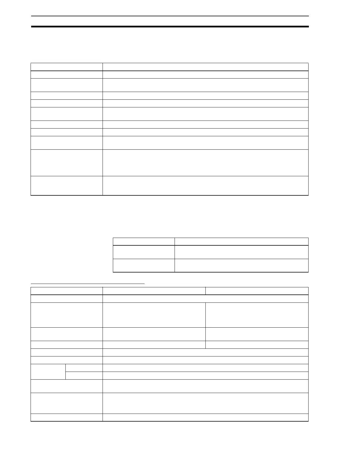
Input Specifications and Functions
Item CJ1W-MAD42
Unit type CJ-series Special I/O Unit
Isolation Between I/O and PLC signals: Photocoupler
(No isolation between individual I/O signals.)
External terminals 18-point detachable terminal block (M3 screws)
Current consumption 580 mA max. at 5 V DC
Dimensions (mm)
(See note 1.)
31 x 90 x 65 (W x H x D)
Weight 150 g max.
General specifications Conforms to general specifications for SYSMAC CJ-series Series.
Mounting position CJ-series CPU Rack or CJ-series Expansion Rack
(Cannot be mounted to a C200H Expansion I/O Rack or a SYSMAC BUS Slave Rack.)
Maximum number of Units
(See note 2.)
CPU Rack: 7 Units max.
Expansion Rack: 8 Units max.
Overall system:
(7 Units max. on CPU Rack) + (8 Units per Expansion Rack × 3 Racks) = 31 Units max.
Data exchange with CPU
Units
Special I/O Unit Area CIO 200000 to CIO295915 (Words CIO 2000 to CIO 2959):
Exchanges 10 words of data per Unit.
Internal Special I/O Unit DM Area (D20000 to D29599)
Power Supply Units Maximum number of Units
CJ1W-PA205R/PD025 CPU Rack: 7 Units max.
Expansion Racks: 8 Units/Rack max.
CJ1W-PA202 CPU Rack: 3 Units max.
Expansion Racks: 4 Units/Rack max.
Item Voltage input Current input
Number of analog inputs 4
Input signal range (See note
3.)
1 to 5 V
0 to 5 V
0 to 10 V
–10 to 10 V
4 to 20 mA
(See note 4.)
Maximum rated input (for 1
point) (See note 5.)
±15 V ±30 mA
External input impedance 1 MΩ min. 250 Ω (rated value)
Resolution 4,000/8,000 (full scale) (See note 8.)
Converted output data 16-bit binary data
Accuracy
(See note 6.)
25°C ±0.2% of full scale
0°C to 55°C ±0.4% of full scale
A/D conversion time (See
note 7.)
1.0 ms/500 µs max. per point
Mean value processing Stores the last “n” data conversions in the buffer, and stores the mean value of the conver-
sion values.
Buffer number: n = 2, 4, 8, 16, 32, 64
Peak value holding Stores the maximum conversion value while the Peak Value Hold Bit is ON.
 Loading...


