240
Wiring Section 6-4
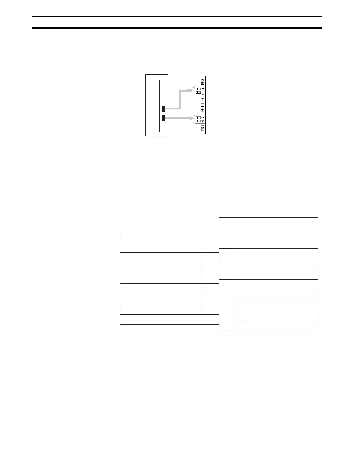
6-3-4 Voltage/Current Switch
The analog conversion input can be switched from voltage input to current
input by changing the pin settings on the voltage/current switch located on the
back of the terminal block.
!Caution Be sure to turn OFF the power to the PLC before mounting or removing the
terminal block.
6-4 Wiring
6-4-1 Terminal Arrangement
The signal names corresponding to the connecting terminals are as shown in
the following diagram.
Note 1. The analog I/O numbers that can be used are set in the Data Memory
(DM).
2. The I/O signal ranges for individual inputs and outputs are set in the Data
Memory (DM). They can be set in units of I/O numbers.
3. The AG terminal (A8, B8) is connected to the 0-V analog circuit in the Unit.
Connecting shielded input lines can improve noise resistance.
4. The N.C. terminals (A5, A11, B5) are not connected to internal circuitry.
IN2: Input 2
IN1: Input 1
OFF: Voltage input
ON: Current input
IN4: Input 4
IN3: Input 3
Output 2 (+) B1
Output 2 (–) B2
Output 4 (+) B3
Output 4 (–) B4
N.C. B5
Input 2 (+) B6
Input 2 (–) B7
AG B8
Input 4 (+) B9
Input 4 (–) B10
A1
A2
A3
A4
A5
A6
A7
A8
A9
A10
A11
Output 1 (+)
Output 1 (–)
Output 3 (+)
Output 3 (–)
N.C.
Input 1 (+)
Input 1 (–)
AG
Input 3 (+)
Input 3 (–)
N.C.