233
Operating Procedure Section 6-2
Creating I/O Tables
After turning ON the power to the PLC, be sure to create the I/O tables.
Initial Data Settings
1,2,3... 1. Specify the Special I/O Unit DM Area settings. Refer to DM Allocation and
Contents on page 246 for further details.
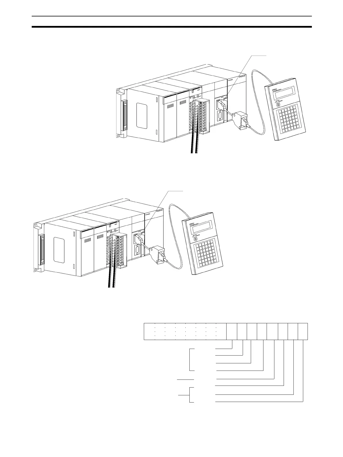
• The following diagram shows the input and output settings used. Refer
to 6-6-1 Input Settings and Conversion Values or 6-7-1 Output Settings
and Conversions for more details.
Peripheral port
Peripheral port
Setting conditions
Unit No. 1
Analog input 1: 1 to 5 V
Analog input 2: 0 to 10 V
Analog input 3: 4 to 20 mA
Analog input 4: 4 to 20 mA
Analog output 1: 1 to 5 V
Analog output 2: 1 to 5 V
Analog output 3: –10 to 10 V
Analog output 4: Not used.
15 14 13 12 11 10 09 08 07 06 05 01 0004 03 02
0 0 0 0 0 0 0 0 1 1 1 1 0 1 1 1
Bit
All used
Input 4
Input 3
Input 2
Input 1
Not used
Output 4
Output 3
Output 2
Output 1
Used
m: DM20100
(00F7 Hex)
 Loading...


