3-61
3 Data Exchange with the CPU Unit
CJ-series DeviceNet Units Operation Manual for NJ-series CPU Unit(W497)
3-3 Device Variables for CJ-series Unit (Allocations
Setting Table, Slave Detailed Status)
3
3-3-7 Slave Detailed Status
z Areas and Word Ranges
Note You cannot use Holding Area H512 and its subsequent holding areas, or EM Area Bank D and its subse-
quent banks.
Various types of statuses of each slave controlled by the master communication are provided.
The following device variables for CJ-series Unit are used to reference all information of the device vari-
ables for CJ-series Unit detailed slave status table.
*_SlavAlocRefTblSta[11] UINT R Slave IN 2
area size
Stores the first word for IN 2 area.
The OUT 1 block is not allocated if the
value is 0.
Data range: 0 to 200
Default: 0
Code Area name in Memory for CJ-series Units Word range
0 --- The block is not used.
1 CIO Area (CIO) 0 to 6143
3 Data Memory (DM) 0 to 32767
4 Work Area (WR) 0 to 511
5 Holding Relay (HR) 0 to 511
8 to 20 Expansion Data Memory (EM)
Bank 0 to bank C (13 banks)
0 to 32767 (E0_00000 to E0_32767, ...,
EC_00000 to EC_32767) for all banks
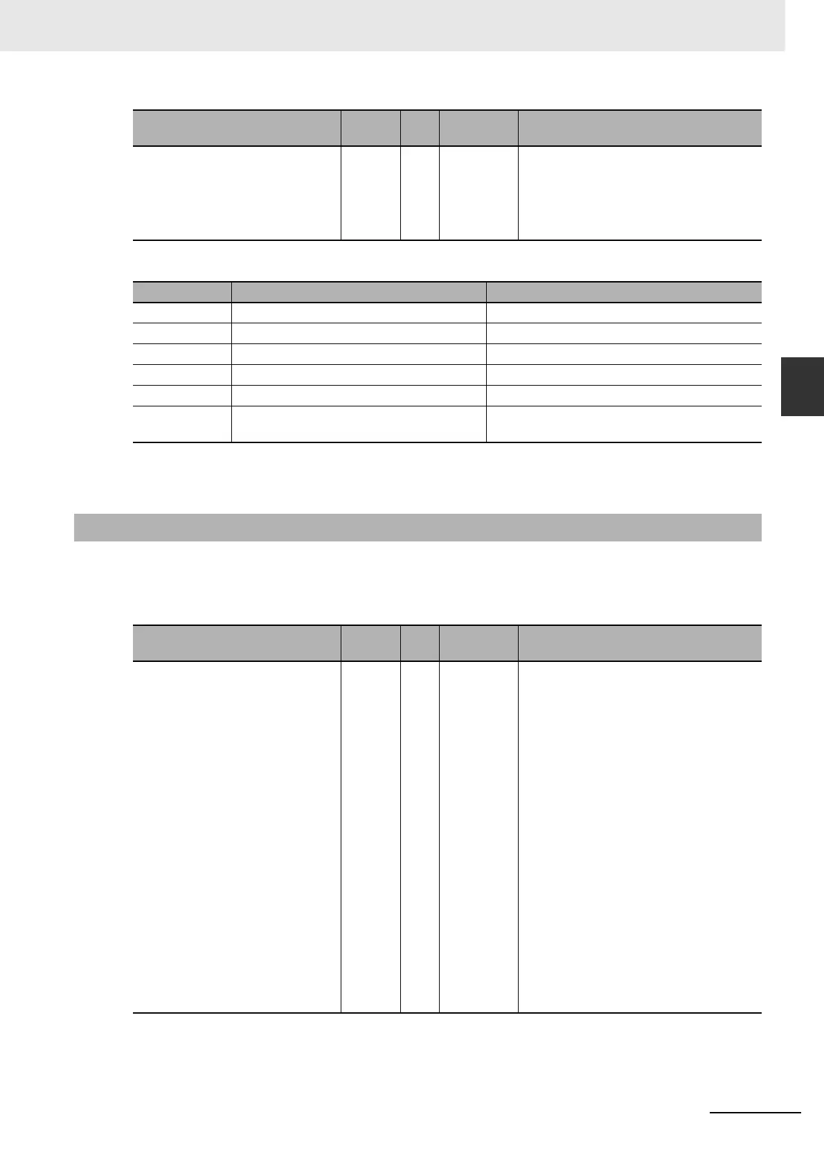
3-3-7 Slave Detailed Status
Name of device variable for
CJ-series Unit
Type R/W Area Function
*_Nd0Sta
to
*_Nd63Sta
BYTE R Detailed
Slave Sta-
tus Table for
Node
Addresses
0 to 63
Each bit of *_Nd0Sta to *_Nd63Sta indi-
cates the following statuses for slaves at
node addresses 0 to 63.
Bit 00: Slave Error for node addresses 0 to
63
Bit 01: Slave Verification Error Flag at
node addresses 0 to 63
Bit 02: Slave Configuration Error for node
addresses 0 to 63
Bit 03: Slave Remote I/O Communications
Error for node addresses 0 to 63
Bit 04: Reserved by system
Bit 05: Master COS Send Error for node
addresses 0 to 63
Bit 06: Scan List Registration Flag for
node addresses 0 to 63
Bit 07: Remote I/O Communications Flag
for node addresses 0 to 63
Data range: 16#00 to FF
Default: 16#00
Name of device variable for
CJ-series Unit
Type R/W Area Function