8-7
8 Communications Timing
CJ-series DeviceNet Units Operation Manual for NJ-series CPU Unit(W497)
8-1 Remote I/O Communications Characteristics
8
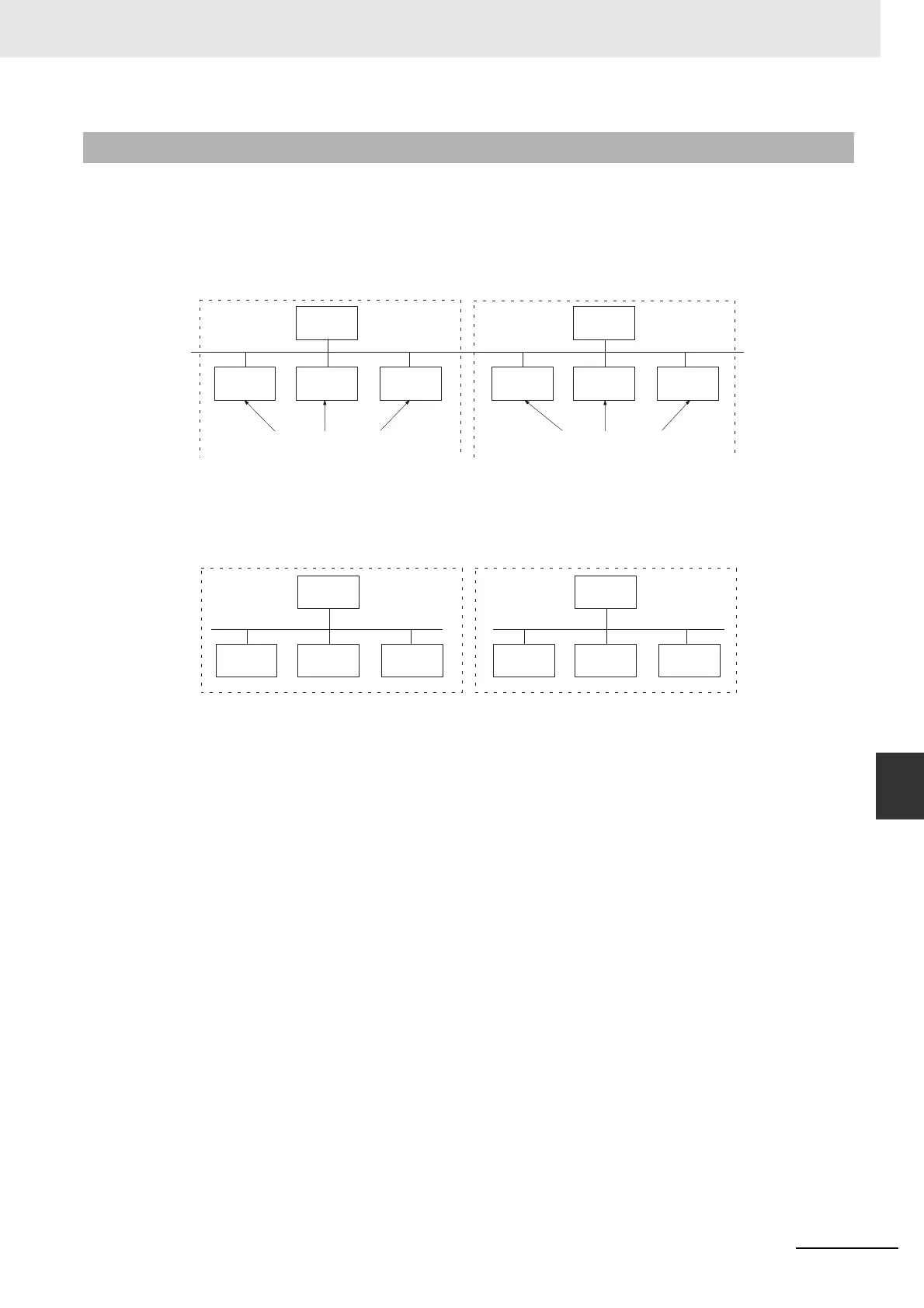
8-1-3 More than One Master in Network
The following equation shows the remote I/O communications cycle time (T
RM
) when there is more than
one master in the network. An example for two masters is used.
First, the network is divided into two groups: Master A and the slaves in remote I/O communications
with it and master B and the slaves in remote I/O communications with it.
Although in the above diagram the Slaves are separated into two groups for convenience, the actual
physical positions in the Network are irrelevant.
Next, we can refer to Communications Cycle Time on page 8-2 and calculate the communications cycle
time for each group as if they were separate Networks.
In Networks with two Masters, the communications cycle time for the entire Network will be the sum of
the communications cycle times for the groups.
T
RM
= T
RM-A
+ T
RM-B
Although this example shows only two Masters in the Network, the total communications cycle time for
any Network can be calculated by dividing it into groups and adding the communications cycle times of
all groups.
8-1-3 More than One Master in Network
Group A
Master A
Slave A
Slave B
Slave C
Slaves in remote I/O commu-
Group B
Master B
Slave D Slave E
Slave F
Slaves in remote I/O commu-
Master A
Group A communications
cycle time: T
RM-A
Group A communications
cycle time: T
RM-B
Group A
Slave A
Slave B
Slave C
Group B
Master B
Slave D Slave E
Slave F