5 Remote I/O Slave Communications
5-12
CJ-series DeviceNet Units Operation Manual for NJ-series CPU Unit(W497)
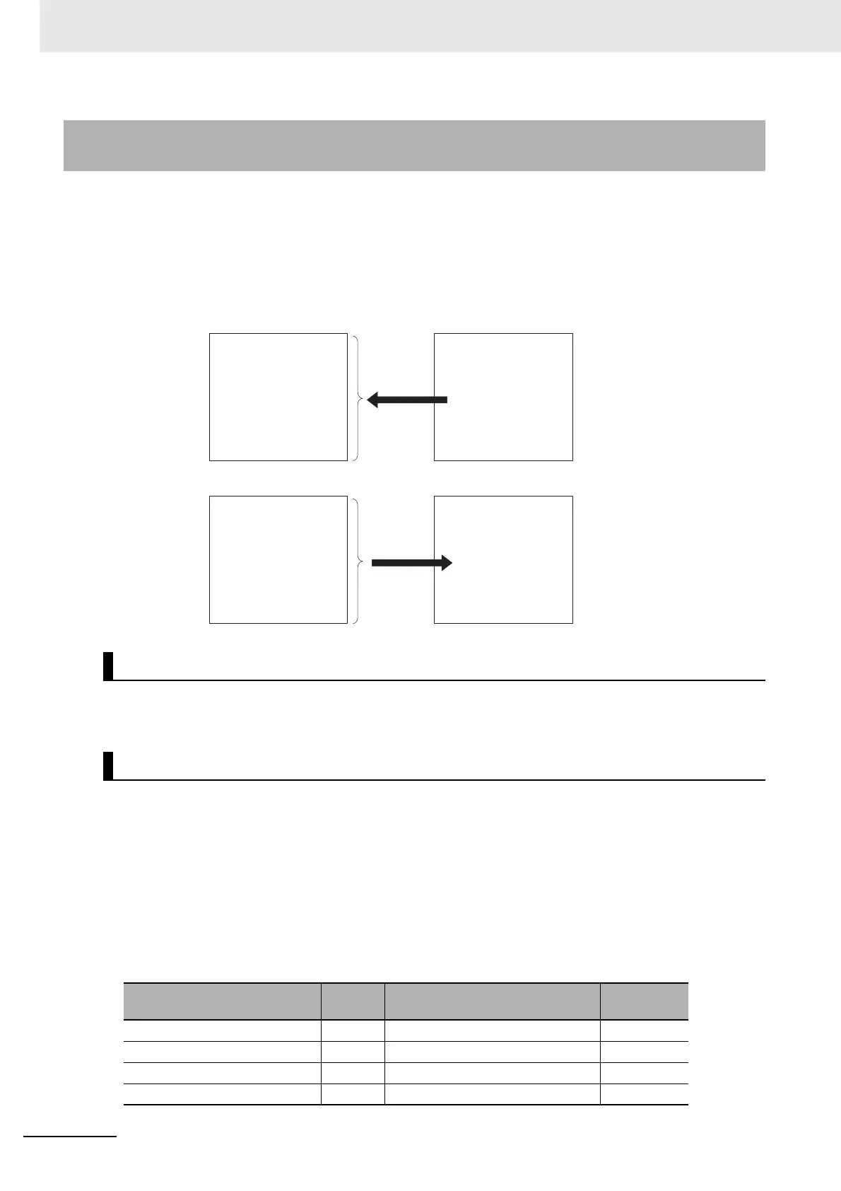
You can allocate words for the OUT 1 area (master to Slave Unit) and IN 1 area (Slave Unit to mas-
ter) from any specified location for the memory used for CJ-series Unit specified in the settings in the
device variables for CJ-series Unit. To access a slave allocated to the memory used for CJ-series
Unit from the user program, user-defined variables that specify the AT specification of the memory
used for CJ-series Unit to which the slave is allocated must be defined.
The type of connection cannot be specified when the device variables for CJ-series Unit is used for set-
tings. The master specifies a poll, bit-strobe, COS, or cyclic connection.
Step 1: Set the CPU Unit to PROGRAM Mode.
Step 2: Stop Slave Communications
If the Unit already functions as a slave, change *_Sw2SlavDsblCmd (Slave Stop Switch) to TRUE to
stop slave communications. This step is not necessary if slave communications are stopped.
Step 3: Set the Slave User-set Allocations Table
This table is used to specify the areas, first words, and sizes for OUT block 1 and IN block 1 to the
device variables for CJ-series Unit below.
• Slave User-set Allocations Setup Table
5-3-2 Settings through Device Variables for CJ-series Unit (Slave User-
set Allocations Setup Table)
Connection Types
Allocation Procedures
Name of device variables for
CJ-series Unit
Type Name Range
*_SlavAlocTblCfg[0] UINT Slave OUT 1 area 0 to 20
*_SlavAlocTblCfg[1] UINT First word in slave OUT 1 area 0 to 32767
*_SlavAlocTblCfg[2] UINT OUT 1 area size 0 to 200
*_SlavAlocTblCfg[3] UINT Slave IN 1 area 0 to 20
Specified areas in memory used for CJ-series Unit
Slave
Bit
First word
specified
OUT 1 area OUT area
Master
IN area
IN 1 area
15 0
to
Bit
First word
specified
15 0
to