4 Remote I/O Master Communications
4-26
CJ-series DeviceNet Units Operation Manual for NJ-series CPU Unit(W497)
Step 1: Set the CPU Unit to PROGRAM Mode.
Step 2: Set the Master Enable Switch to TRUE.
Make sure that master communications was disabled by checking to see if *_MstrEnblSta (Master
Function Enabled Status) is FALSE, and then set to TRUE the *_Sw1MstrEnblCmd (Master Enable
Switch) to enable master communications. Once you have turned this switch from OFF to ON, which
will enable the master, the system operates over the master whether the power supply is turned OFF
or ON.
Note Do not change the Master Enable Switch to TRUE unless master communications are
stopped. (If the Master Enable Switch is change to TRUE when master communications are
enabled, a Unit error will occur and a "C5" error will be displayed on the 7-segment indicator
on the front panel.)
Step 3: Set the Master User-set Allocations Setup Table
This table specifies the area and first word for each block and the area and first word for the Alloca-
tion Size Setup Table.
• Master User-set Allocations Setup Table
• Areas and Word Ranges for OUT Block 1, IN Block 1, and the Allocation Size Setup Table
Note You cannot use Holding Area H512 and its subsequent holding areas, or EM Area Bank D and its subse-
quent banks.
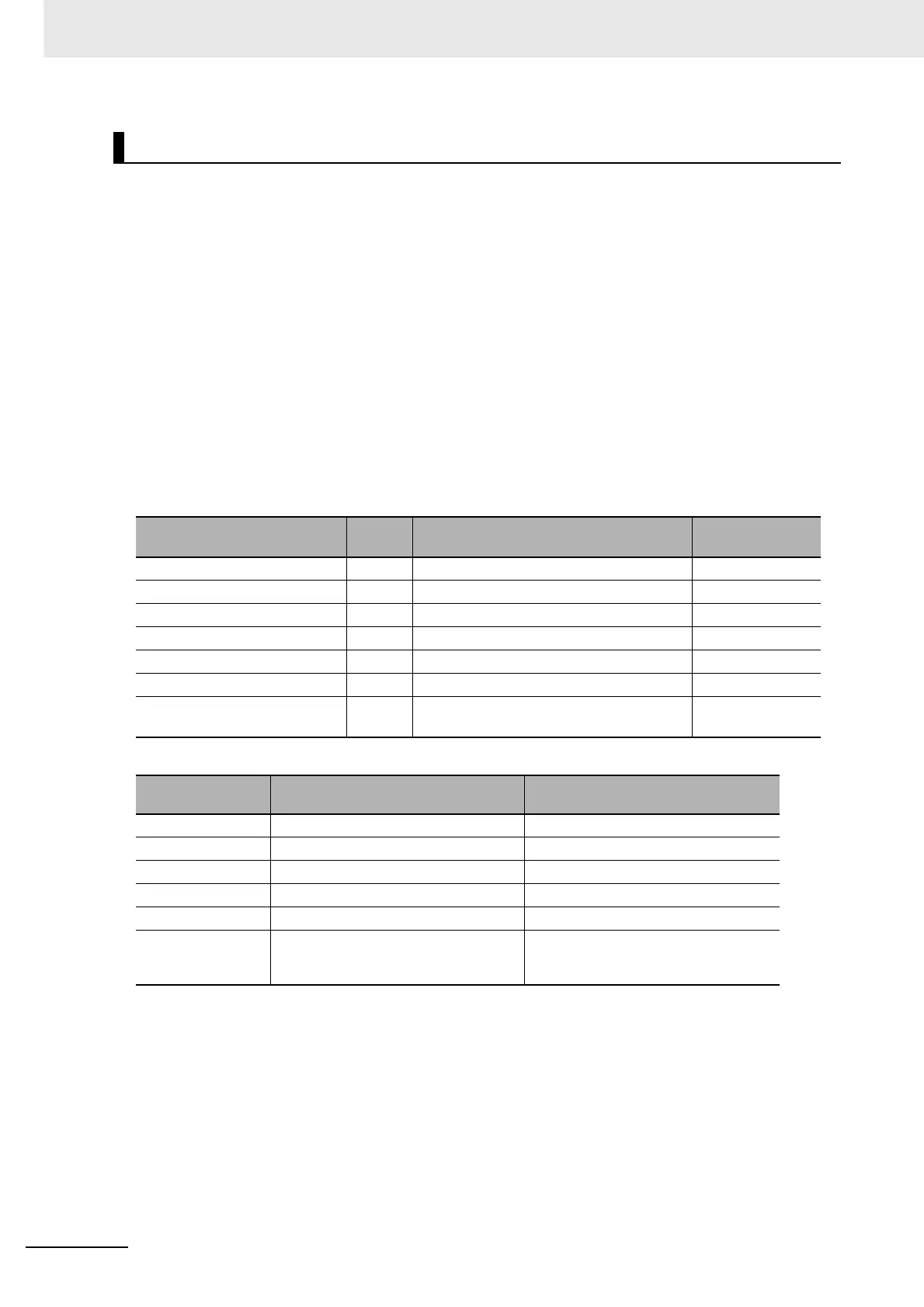
Allocation Procedures
Name of device variables for
CJ-series Unit
Type Name Range
*_MstrAlocTblCfg[0] UINT OUT block 1 area 0 to 20
*_MstrAlocTblCfg[1] UINT First word in OUT block 1 0 to 32767
*_MstrAlocTblCfg[2] UINT IN block 1 area 0 to 20
*_MstrAlocTblCfg[3] UINT First word in IN block 1 0 to 32767
*_MstrAlocTblCfg[4] UINT Allocation size setup table area 0 to 20
*_MstrAlocTblCfg[5] UINT First word in allocation size setup table 1 0 to 32767
*_MstrAlocTblCfgSta WORD Setting Results of Master User-set Alloca-
tions Setup
16#0000 to FFFF
Code Area name in memory used
for CJ-series Unit
Word range
0 --- The block is not used.
1 CIO Area (CIO) 0 to 6143
3 Data Memory (DM) 0 to 32767
4 Work (WR) 0 to 511
5 HR (HR) 0 to 511
8 to 20 Expansion Data Memory (EM)
Bank 0 to bank C (13 banks)
0 to 32767 (E0_00000 to E0_32767,
... , EC_00000 to EC_32767) for all
banks