Appendices
A-18
CP1E CPU Unit Hardware User’s Manual(W479)
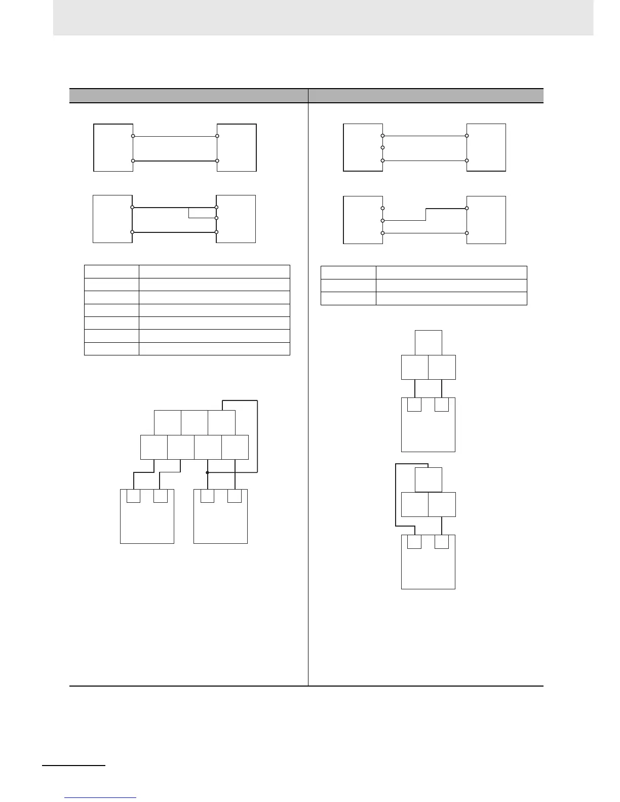
Analog Input Wiring Diagram Analog Output Wiring Diagram
Note 1 Use 2-conductor shielded twisted-pair cable for the
I/O wiring, and do not connect the shield AG termi-
nal.
2 If an input is not being used, connect (short) the
input’s + and - terminals.
3 Wire I/O lines apart from power lines (AC power sup-
ply lines, three-phase power lines, etc.).
4 If noise is received from power supply lines, insert a
noise filter in the power supply input section.
5 When noise disturbs the analog input/output cable,
install the core to improve anti-noise performance.
+
COM
Voltage Input
−
Analog
output
device
(voltage
output)
V IN
Analog
Input
Terminal
Block
+
COM
Current Input
−
V IN
I IN
Analog
output
device
(current
output)
Analog
Input
Terminal
Block
VIN0 Analog input 0 voltage input
IIN0 Analog input 0 current input
COM0 Analog input 0 common
AG Analog 0V
VIN1 Analog input 1 voltage input
IIN1 Analog input 1 current input
COM1 Analog input 1 common
IIN0
VIN0 COM0 VIN1 COM1
AG IIN1
+- +-
Analog output
device
(Voltage output)
Analog output
device
(Current output)
V OUT
COM
I OUT
V OUT
COM
I OUT
+
−
+
−
Analog
Output
Terminal
Block
Analog
input
device
(voltage
input)
Analog
Output
Terminal
Block
Analog
input
device
(current
input)
Voltage Output
Current Output
VOUT0 Analog output 0 voltage output
IOUT0 Analog output 0 current output
COM0 Analog output 0 common
IOUT0
VOUT0 COM0
IOUT0
VOUT0 COM0
Analog input
device
(Current input)
Analog input
device
(Voltage input)
+-
+-