2-3
2 Basic System Configuration and Devices
CP1E CPU Unit Hardware User’s Manual(W479)
2-1 Basic System Configuration
2
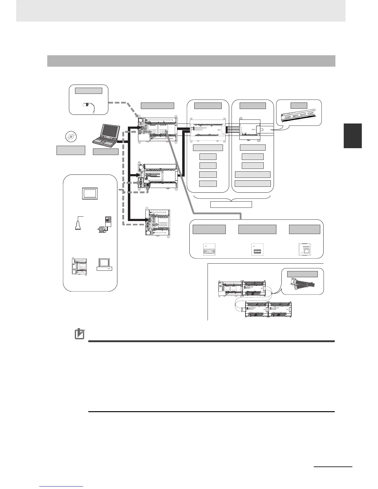
2-1-2 Basic System Configuration Using an N/NA(S)-type CPU Unit
The system configuration when using a CP1E N/NA(S)-type CPU Unit is shown below.
Precautions for Correct UsePrecautions for Correct Use
For CP1E CPU Units, the following I/O memory area will be unstable after a power interruption.
• DM Area (D) (excluding words backed up to the EEPROM using the DM function)
• Holding Area (H)
• Counter Present Values and Completion Flags (C)
• Auxiliary Area related to clock functions(A)
Mount the CP1W-BAT01 Battery (sold separately) to an N/NA(S)-type CPU Unit if
data in the above areas need to be retained after a power interruption. A Battery cannot be
mounted to an E(S)-type CPU Unit.
2-1-2 Basic System Configuration Using an N/NA
(S
)-type CPU Unit
CP1E-N30S(1)D-
CP1E-N40S(1)D-
CP1E-N60S(1)D-
CP1E-N14D-
CP1E-N20D-
CP1E-N30D-
CP1E-N40D-
CP1E-N60D-
CP1E-NA20D-
CP1E CPU Unit
Expansion I/O Units Expansion Units
8 inputs
8 outputs
16 outputs
32 outputs
Analog I/O
Analog inputs
Analog outputs
Temperature sensors
CompoBus/S I/O Link Unit
Up to 3 Units can be connected
DIN Track
CP1W-CN811
CP1E CPU Unit
Expansion Units and
Expansion I/O Units
I/O Connecting Cable
Personal computer
Support Software
CX-Programmer
IBM PC/AT or equivalent
COMM
RS-232C Option Board
CP1W-CIF01
COMM
RS-422A/485 Option Board
CP1W-CIF11
CP1W-CIF12
IP ADDRESS:
SUBNET MASK:
COMMERR
10BASE-T
100BASE-TX
Ethernet Option Board
CP1W-CIF41
(version 2.0 or higher)
Or Or
Battery
CP1W-BAT01
When a two level layout is created by expansion and distance is required
(NT Link/Host Link)
General component
(No-protocol mode)
(Modbus-RTU)
CP-series PLC or
CJ1M PLC
(Serial PLC Link)
Host computer
(Host Link)
Programmable
Terminal (PT)
*Neither the CP1W-DAM01 LCD Option Board nor the CP1W-CIF41
Ethernet Option Board version 1.0 can be used.
Inverter
20 or 40 I/O Points