5 Installation and Wiring
5-6
CP1E CPU Unit Hardware User’s Manual(W479)
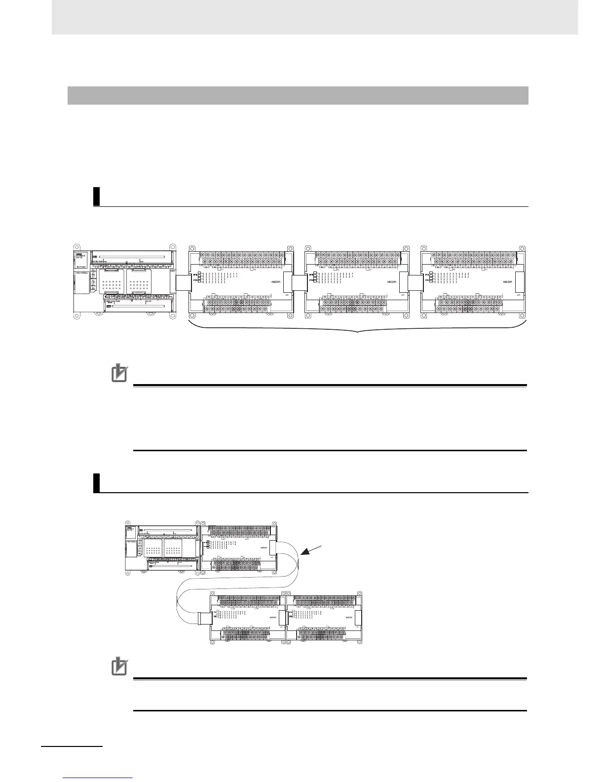
This section describes how to arrange the CP1E Units.
As shown in the following diagrams, Units can be arranged in one or two rows when Expansion I/O
Units or Expansion Units are used.
Expansion I/O Units and Expansion Units can be installed in a side-by-side arrangement.
Precautions for Correct UsePrecautions for Correct Use
When connecting CP-series Expansion Units or Expansion I/O Units to a CPU Unit with AC
power, provide a space of approximately 10 mm between the CPU Unit and the first Expansion
Unit or Expansion I/O Unit.
If sufficient space cannot be provided between the CPU Unit and the first Expansion Unit or
Expansion I/O Unit, use the PLC in an ambient temperature of 0 to 50°C.
The Units can be arranged in two rows using the CP1W-CN811 I/O Connecting Cable (800 mm).
Precautions for Correct UsePrecautions for Correct Use
I/O Connecting Cable can be used in one place only in each CP1E PLC. It cannot be used in
more than one place in the same CP1E PLC.
5-2-2 Unit Arrangement
Arrangement in One Row
Arrangement in Two Rows
CP-series Expansion Units and Expansion I/O Units
CP1E CPU Unit
CP1W-CN811 I/O
Connecting Cable