3 Part Names and Functions
3-22
CP1E CPU Unit Hardware User’s Manual(W479)
z DIP switch for operation settings
z LED Indicators
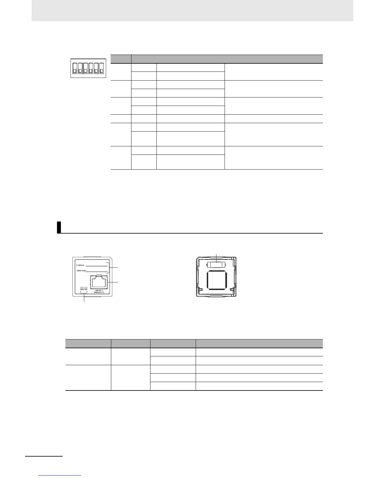
z Ethernet Connectors
The following standards and specifications apply to the connectors for the Ethernet twisted-pair
cable.
Electrical specifications: Conforming to IEEE802.3 standards
Pin Setting
1 ON ON (both ends) Terminating resistance selection
Resistance value:220Ω typical
OFF OFF
2 ON 2-wire connections
2-wire or 4-wire selection
*1
OFF 4-wire connections
3 ON 2-wire connections
2-wire or 4-wire selection
*1
OFF 4-wire connections
4 −−Not used.
5 ON RS control enabled
RS control selection for RD
*2
OFF RS control disabled (Data
always received.)
6 ON RS control enabled
RS control selection for SD
*3
OFF RS control disabled (Data
always sent.)
*1 Set both pins 2 and 3 to either ON (2-wire) or OFF (4-wire).
*2 To disable the echo-back function, set pin 5 to ON (RS control enabled).
*3 When connecting to a device on the N side in a 1: N connection with the 4-wire method,
set pin 6 to ON (RS control enabled).
Also, when connecting by the 2-wire method, set pin 6 to ON (RS control enabled).
CP1W-CIF41 Ethernet Option Board
Indicator Color Status Meaning
COMM Yellow Not lit Not sending or receiving data.
Flashing Sending or receiving data.
ERR Red Not lit Unit normal.
Lit An fatal error has occurred at the Unit.
Flashing An no-fatal error has occurred at the unit.
1
2
3
4
5
6
O
N
Label
Attach the label here to show IP
address and subnet mask.
Front Rear
CPU Unit connector
Ethernet Connector
Used to connect the Ethernet
twisted-pair cable.
LED Indicators
Display the operating status of the Option Board.