3-23
3 Part Names and Functions
CP1E CPU Unit Hardware User’s Manual(W479)
3-1 CPU Units
3
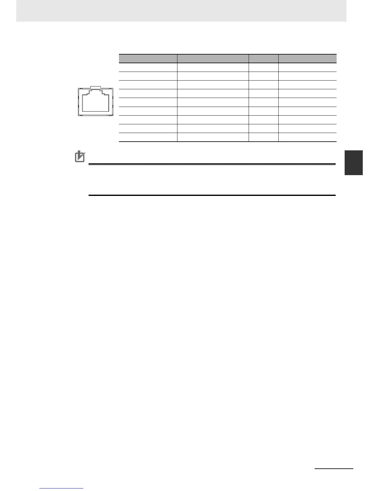
3-1-4 Optional Serial Communications Port for N/NA(S)-type CPU Units
Connector structure: RJ45 8-pin Modular Connector (conforming to ISO8877)
Precautions for Correct UsePrecautions for Correct Use
Connecting the Cable
• Turn OFF the PLC’s power supply before connection or disconnecting twisted-pair cable.
• Allow enough space for the bending radius of the twisted-pair cable.
Connector Pin Signal Name Abbr. Signal Direction
1 Transmission data + TD+ Output
2 Transmission data - TD- Output
3 Reception data + RD+ Input
4 Not used --- ---
5 Not used --- ---
6 Reception data - RD- Input
7 Not used --- ---
8 Not used --- ---
Hood Frame ground FG ---