E3X-DAC-S
13
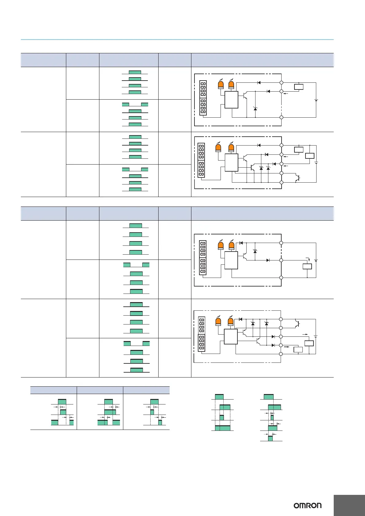
Output Circuit Diagrams
NPN Output
PNP Output
Note:1.Timing Charts for Timer Function Settings (T: Set Time) 2. Control Output (AND, OR, Sync) and Timing Chart for Timer Settings
(T: Set Time)
Model
Operation
mode
Timing charts
Operation
selector
Output circuit
E3X-DAC11-S
E3X-DAC6-S
ON for
match
LIGHT ON
(L-ON)
ON for mis-
match
DARK ON
(D-ON)
E3X-DAC21-S
E3X-DAC21B-S
ON for
match
LIGHT ON
(L-ON)
ON for mis-
match
DARK ON
(D-ON)
Match
Mismatch
ON
OFF
ON
OFF
Operate
Reset
(Between brown and black leads)
Operation
indicator
(orange)
Output
transistor
Load
(relay)
Load
I mode indicator (orange)
Brown
Black
Blue
Control output
12 to
24 VDC
Display
Photo-
electric
Sensor
main
circuit
Operation
indicator
(Orange)
Match
Mismatch
ON
OFF
ON
OFF
Operate
Reset
(Between brown and black leads)
Operation
indicator
(orange)
Output
transistor
Load
(relay)
Match
Mismatch
ON
OFF
ON
OFF
Operate
Reset
(Between brown and black leads)
Operation
indicator
(orange)
Output
transistor
Load
(rela
y)
Orange
Pink
Load
External input
(Bank switching
input) *
Brown
Black
Blue
12 to
24 VDC
Display
Photo-
electric
Sensor
main
circuit
Ch1
operation
indicator
(orange)
Ch2 operation indicator
(orange)
Load
Ch2 control output
Ch1
control output
Match
Mismatch
ON
OFF
ON
OFF
Operate
Reset
(Between brown and black leads)
Operation
indicator
(orange)
Output
transistor
Load
(relay)
Model
Operation
mode
Timing charts
Operation
selector
Output circuit
E3X-DAC41-S
E3X-DAC8-S
ON for
match
LIGHT ON
(L-ON)
ON for mis-
match
DARK ON
(D-ON)
E3X-DAC51-S
E3X-DAC51B-S
ON for
match
LIGHT ON
(L-ON)
ON for mis-
match
DARK ON
(D-ON)
Match
Mismatch
ON
OFF
ON
OFF
Operate
Reset
(Between blue and black leads)
Operation
indicator
(orange)
Output
transistor
Load
(rela
y)
Control output
Brown
Black
Blue
12 to
24 VDC
Display
Photo-
electric
Sensor
main
circuit
Operation
indicator
(Orange)
Load
I mode indicator (orange)
Match
Mismatch
ON
OFF
ON
OFF
Operate
Reset
(Between blue and black leads)
Operation
indicator
(orange)
Output
transistor
Load
(rela
y)
Match
Mismatch
ON
OFF
ON
OFF
Operate
Reset
(Between blue and black leads)
Operation
indicator
(orange)
Output
transistor
Load
(relay)
Brown
Black
Blue
12 to
24 VDC
Display
Photo-
electric
Sensor
main
circuit
Load
Load
Orange
Pink
Ch1
operation
indicator
(orange)
Ch2 operation indicator (orange)
Ch2 control output
Ch1 control output
External input
(Bank switching
input) *
Match
Mismatch
ON
OFF
ON
OFF
Operate
Reset
(Between blue and black leads)
Operation
indicator
(orange)
Output
transistor
Load
(rela
y)
ON delay OFF delay One-shot
Match
Mismatch
ON
OFF
ON
OFF
L-ON
D-ON
T
T
Match
Mismatch
ON
OFF
ON
OFF
L-ON
D-ON
T
T
Match
Mismatch
ON
OFF
ON
OFF
L-ON
D-ON
T
T
CH1
CH2
ON
OFF
ON
OFF
ON
OFF
ON
OFF
OUT
(OR)
OUT
(AND)
CH1
CH2
ON
OFF
ON
OFF
ON
OFF
ON
OFF
ON
OFF
One-shot
(AND)
OFF delay
(AND)
ON delay
(AND)
T
T
T

 Loading...