E3X-DAC-S
21
Judgment mode
(Used to set the judgment
mode)
MODE
SET
5
*
When the settings
have been completed
Set the SET/RUN
Mode Selector Switch to .
RUN
RUN
Timer
Display orientation
(To reverse the orientation
of the display.)
(To use the timer setting)
Operation mode
(To set the operation mode)
Display switch
(To change the display
method)
Teaching level
(To change the teaching
level)
MODE key
(To change the function of the
MODE key during operation)
Output setting
(To change the channel 2
output)
External input
(To change function controlled
by external input.)
Detection
(To increase the response
speed or detection precision)
Teaching
External input memory
(Refer to instructions
provided with the product.)
Set the SET/RUN
Mode Selector to SET.
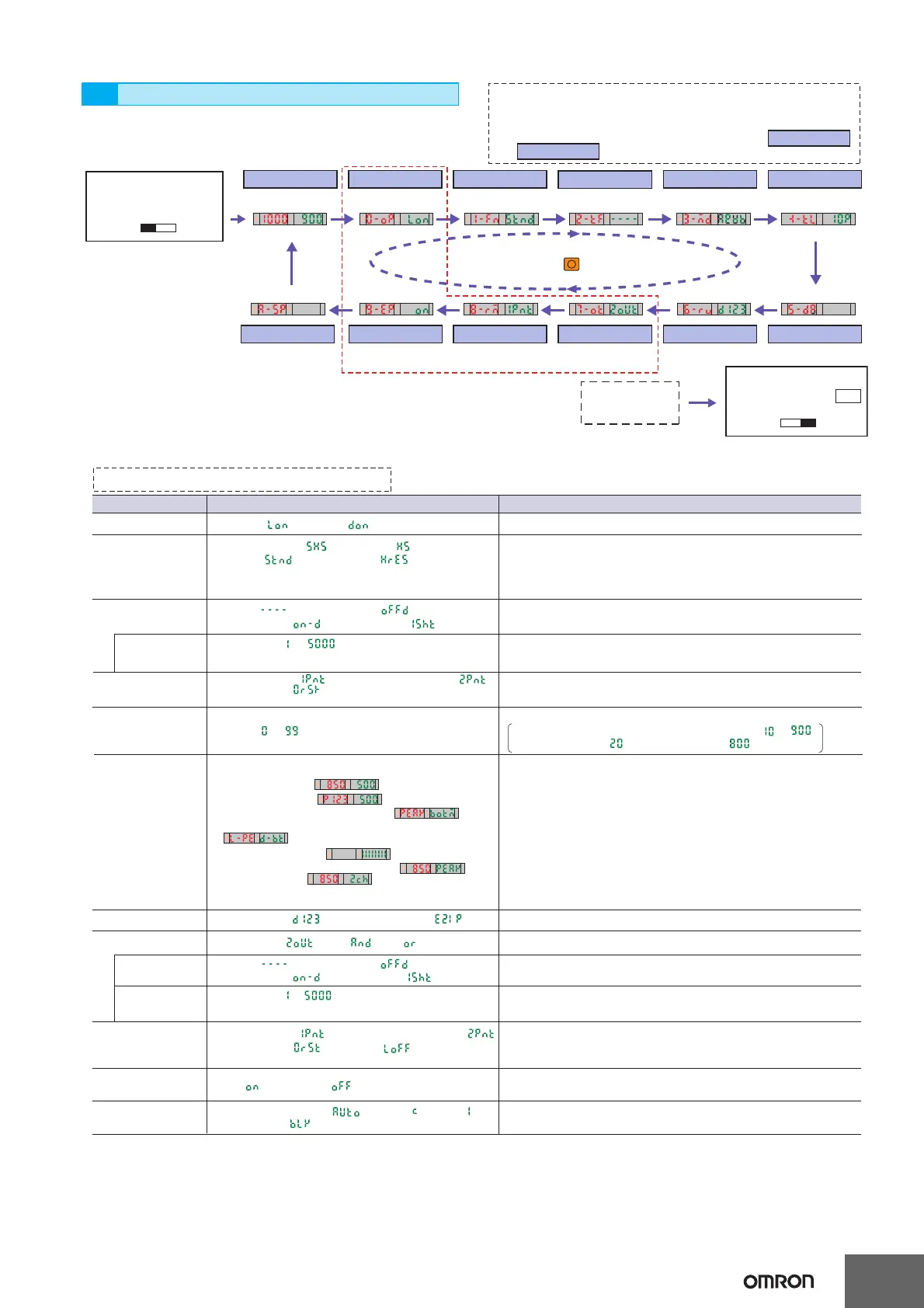
Function Transitions
*. The displays shown in the function transitions are for the default settings.
*.
Items shown in the function transitions may increase depending on detailed settings.
*. The items enclosed by dotted red lines are for advanced models only.
(Advanced models with four-color determination do not have
or .)
External input
External input memory
➜ Page 20
Refer to 2. Registering Workpiece
Colors with Teaching in SET Mode.
Setting Functions in SET Mode
C/I automatic judgment: , C mode: , I mode:
BLACK mode:
1 to 5000 ms: to
(1 to 20: 1-ms increments, 20 to 200 ms: 5-ms increments,
200 to 1000: 100-ms increments, 1000 to 5000: 1000-ms increments)
1-point teaching: ,
Teaching without workpiece
:
Zero-shift reset: , Light OFF:
Enabled: , OFF-delay timer:
ON-delay timer: , One-shot timer:
Enabled: , OFF-delay timer:
ON-delay timer: , One-shot timer:
Settings (display) Function Description
Used to increase the response speed or detection precision.
Detection
Timer
MODE key
Operation mode
Super-high-speed: , High-speed: ,
Standard: , High-resolution:
Normal display: , Upside down display:
1-point teaching: , Teaching with workpiece:
Zero-shift reset:
Match: ON , Mismatch:
Each channel: , AND: , OR:
Use the UP and DOWN Keys to change the settings.
Used to change the function of the MODE key during
operation.
1 to 5000 ms: to
(1 to 20: 1-ms increments, 20 to 200 ms: 5-ms increments,
200 to 1000: 100-ms increments, 1000 to 5000: 1000-ms increments)
Timer time
(timer enabled)
Used to change timer times.
The timer can be set from 1 ms to 5 s.
Teaching level
Display switch
Output setting
Timer function
Timer time
Used to change the orientation of the display.
Display orientation
Example: The threshold level at the default setting ( ) is .
When the setting is , the threshold level is .
Used to change the item output on control output 2.
0 to 99P: to
Write: , Do not write:
Used to set whether to write the control results to memory.
(Refer to the instructions provided with the product.)
Used to change timer time.
The timer can be set from 1 ms to 5 s.
External input memory
External input
Used to set the judgment mode (detection method). BLACK mode:
The total light intensity for red, green, and blue is used for the judgment.
Judgment mode
Used to set timers for the AND/OR control output.
Functions
Used to set control output timers.
(1) Match/threshold:
(2) Margin/threshold:
(3) Peak/Bottom refreshed every 2 s:
(4) Peak/Bottom refreshed every time the output is switched:
(5) Analog bar display:
(6) Match/peak (updated periodically):
(7) Match/channel:
Note: If the detection function is changed, be sure to
teach the workpiece color.
Note: Only I Mode (light intensity determination for red, green, or blue)
can be used with Super-high-speed mode.
Used to change the threshold setting level during 1-point teaching.
1. Used to display the degree of matching and the threshold.
2. Used to display the excess gain (i.e., percentage of matching relative
to threshold) and the threshold.
3. Used to display the peak and bottom degrees of matching at a fixed
interval.
4. Used to display the peak degree of matching when there is a match
and the bottom degree of matching when there is no match.
5. Used to show the detection status with a bar display. Red bars will be
displayed if the degree of match exceeds the threshold.
6. Used to display the present degree of matching and the peak degree
of matching.
7. Used to display the degree of matching and channel number.
Used to change the functions to be remotely controlled with external input.
(For the effective pulse width and other information, refer to the
instructions provided with the product.)
➜ Page 20 Refer to 2. Setting the Operation Mode.
➜ Page 22 Refer to 6-1. Zeroing the Display (Zero Reset).

 Loading...