92
Setting Scaling Upper and Lower Limits for Analog Inputs Section 4-3
4-3 Setting Scaling Upper and Lower Limits for Analog Inputs
4-3-1 Analog Input
• When an analog input is selected, scaling can be performed as needed
by the control application.
• Scaling is set in the Scaling Upper Limit, Scaling Lower Limit, and Deci-
mal Point parameters (initial setting level). These parameters cannot be
used when a temperature input is selected.
• The Scaling Upper Limit parameter sets the physical quantity to be
expressed by the upper limit value of input, and the Scaling Lower Limit
parameter sets the physical quantity to be expressed by the lower-limit
value of input. The Decimal Point parameter specifies the number of digits
below the decimal point.
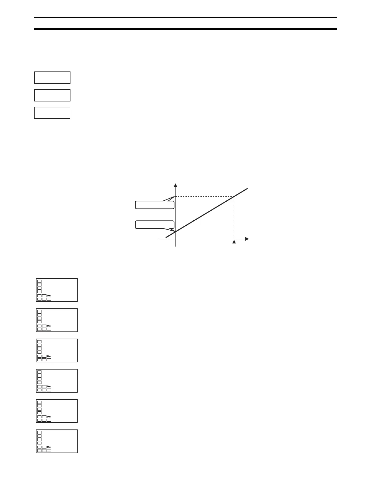
• The following figure shows a scaling example for a 4 to 20-mV analog
input. After scaling, the temperature can be directly read. The decimal
point is set to 1.
Operating Procedure In this example scaling is set to display 4 to 20 mA as 10.0% to 95.0%.
in-h
in-l
dp
Scaling Upper Limit
Scaling Lower Limit
Decimal Point
4
20
Display
(humidity)
Upper limit (95.0%)
Lower limit (10.0%)
Input (mA)
Initial Setting Level
1. Press the O Key for three seconds to move from the operation level to
the initial setting level.
2. Press the U and D Keys to set 25.
3. Select Scaling Upper Limit parameter by pressing the M Key.
4. Use the U and D Keys to set the parameter to 950.
5. Select the Scaling Lower Limit parameter by pressing the M Key.
6. Press the U and D Keys to set 100.
in-t
5
Input Typ
in-t
25
in-h
100
Scaling Upper
Limit
in-h
950
in-l
0
Scaling Lower
Limit
in-l
100