67
Alarm Outputs Section 3-9
Note Proportional Action
When PID constants I (integral time) and D (derivative time) are set to 0, con-
trol is executed according to proportional action. As the default, the center
value of the proportional band becomes the set point.
Related parameter: Manual reset value (adjustment level)
3-9 Alarm Outputs
• Alarm outputs are determined by a combination of Alarm Type, Alarm
Value, and Alarm Hysteresis alarm output conditions. For details, refer to
4-2 Alarm Hysteresis.
• This section describes the Alarm Type, Alarm Value, Upper-limit Alarm
and Lower-limit Alarm parameters.
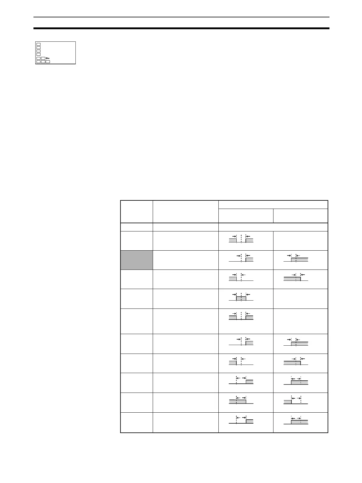
3-9-1 Alarm Types
8. Use the U and D Keys to set 45.0.
9. To return to the operation level, press the O Key.
2.d
45.0
Set value Alarm type Alarm output operation
When alarm value X
is positive
When alarm value X
is negative
0 Alarm function OFF Output OFF
1 Upper- and lower-limit See note 2.
2 (See note
1.)
Upper-limit
3 Lower-limit
4 (See note
1.)
Upper- and lower-limit
range
See note 3.
5 (See note
1.)
Upper- and lower-limit
with standby sequence
See note 4.
6 Upper-limit with standby
sequence
7 Lower-limit with standby
sequence
8 Absolute-value upper-
limit
9 Absolute-value lower-limit
10 Absolute-value upper-
limit with standby
sequence
LH
ON
OFF
SP
X
ON
OFF
SP
ON
OFF
SP
X
X
ON
OFF
SP
X
ON
OFF
SP
LH
ON
OFF
SP
LH
ON
OFF
SP
See note 5.
X
ON
OFF
SP
ON
OFF
SP
X
X
ON
OFF
SP
X
ON
OFF
SP
X
ON
OFF
0
X
ON
OFF
0
ON
OFF
X
0
ON
OFF
X
0
X
ON
OFF
0
X
ON
OFF
0