69
Alarm Outputs Section 3-9
3-9-2 Alarm Values
• Alarm values are indicated by “X” in the table on the previous page. When
the upper and lower limits are set independently, “H” is displayed for
upper limit values, and “L” is displayed for lower limit values.
• To set the alarm upper and lower limits for deviation, set the upper and
lower limits in the Alarm 1 to 3 Upper Limit and Alarm 1 to 3 Lower Limit
parameters.
• Alarm values can be set for each bank. Select the bank number in the
Display Bank Selection parameter in the bank setting level, and set the
Alarm Value, Alarm Value Upper Limit (1 to 3), and Alarm Value Lower
Limit (1 to 3) parameters for that bank.
• When the Alarm Value, Alarm Value Upper Limit, and Alarm Value Lower
Limit parameters in the operation level are changed, the changes will be
reflected in those parameters for the current bank.
Operating Procedure This procedure sets alarm 1 for bank number 1 as an upper-limit alarm. The
related parameters and settings are shown below. The alarm is output when
the set point exceeds 10°C. (In this example, the temperature unit is °C.)
Alarm 1 type = 2 (Upper-limit alarm)
Bank 1 Alarm value 1 = 10
∗
.a1l
∗
.a1h
∗
.a2l
∗
.a2h
∗
.a-1
∗
.a-2
∗
.a3l
∗
.a3h
∗
.a-3
Bank* Alarm Value
Lower Limit
Alarm Value Upper
Limit Value
Alarm Value
(
∗
: 0 to 7)
(
∗
: 0 to 7)
(
∗
: 0 to 7)
Initial Setting Level
1. Press the O Key for at least three seconds to move from the operation
level to the initial setting level.
2. Select the Alarm 1 Type parameter by pressing the M Key. Confirm that
the set value is 2. The default value is 2 (Upper-limit alarm).
3. To return to the operation level, press the O Key for at least one second.
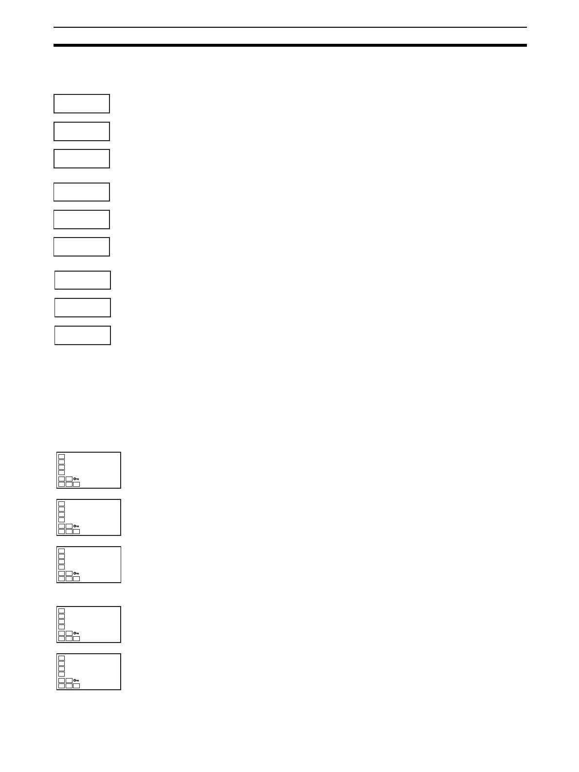
Bank Setting Level
4. Press the O Key to move to the bank setting level.
5. Use the U and D Keys to set 1.
in-t
5
Input Type
alt1
2
Alarm 1 Type
C
25.0
100.0
PV/SP
d.bnk
0
Display Bank
Selection
d.bnk
1