125
Using the Transfer Output Section 4-14
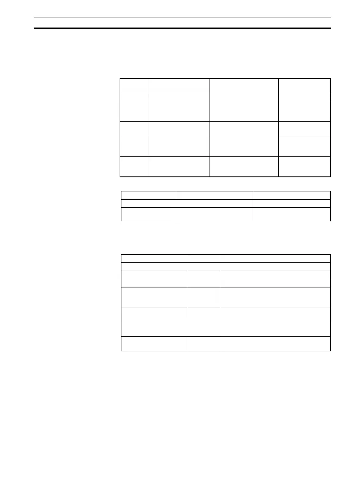
• The operation differs for models with a transfer output and models without
a transfer output for which control output 1 or control output 2 is used as a
simple transfer output, as shown in the following table.
Transfer Output
Destination
■ Precision and User Calibration
Note For details on the calibration method, refer to SECTION 6 CALI-
BRATION.
Transfer Output Type
Note (1) The default is OFF. For a Controller that does not support a transfer out-
put, the item specified for the Control Output 1 Assignment or Control
Output 2 Assignment parameter will be output.
(2) The output value will be different between when the Transfer Output Type
parameter is set to a heating control output or cooling control output, and
when the Control Output 1 Assignment or Control Output 2 Assignment
parameter is set to a heating control output or cooling control output.
Example: When a Current Output Is Set to 4 to 20 mA and MV Monitor
(Heating) Is Selected
When used as a transfer output, 4.0 mA will be output for 0% and
20.0 mA will be output for 100%.
Transfer
output
Control output 1 Control output 2 Transfer output
destination
Yes --- --- Transfer output
No Current output or linear
voltage output
None, relay output, voltage
output (for driving SSR), or
SSR output
Control output 1
No Current output or linear
voltage output
Current output or linear
voltage output
Control output 1
No Relay output, voltage
output (for driving
SSR), or SSR output
Current output or linear
voltage output
Control output 2
No Relay output, voltage
output (for driving
SSR), or SSR output
None, relay output, voltage
output (for driving SSR), or
SSR output
None
Precision User calibration
Transfer output ±0.3% FS Supported. (See note.)
Simple transfer out-
put
Not specified. Not supported.
Transfer output type Symbol Setting range
OFF (See note 1.) off ---
Set point sp SP lower limit to SP upper limit
Set point during SP ramp sp-m SP lower limit to SP upper limit
PV pv Input setting range lower limit to input set-
ting range upper limit or
Scaling lower limit to scaling upper limit
MV monitor (heating)
(See note 4.)
mv −5.0 to 105.0 (heating/cooling control: 0.0 to
105.0) (See note 2.)
MV monitor (cooling)
(See note 5.)
c-mv 0.0 to 105.0 (See note 2.)
Valve opening (See note
6.)
v-m −10.0 to 110.0